

Description
- Brand: ABB
- Full Model Number: 1MSC980119 REV.D
- ABB Ordering Number: 1MRS050639
- ABB Type Designation: RE_54 PS1_240V_MED
- Product Type: Power supply board
- Core Function in System: Internal power conversion and supply for ABB RE_54 / REM 543 protection equipment
- Host Equipment: ABB REM 543 rotating machine terminal
- Output: 24 VDC, 1 A
- Net Weight: 0.44 kg
- Reported Dimensions: 330 × 240 × 29 mm
- Board Revision: REV.D
- Condition & Lead Time: Stock condition subject to inspection; emergency dispatch available subject to order confirmation
ABB’s product record identifies 1MRS050639 as PS1_240V_MED, with a product name of PS1_240V_MED, a 0.44 kg net weight, and classification as a spare part. A technical product listing associates the board with RE_54_PS1_240V MED, the REM 543 rotating machine terminal, and reports 24 VDC / 1 A output.
Module 3: Technical Intro & Downtime Impact
A protection-terminal power-supply failure can take the entire monitoring and protection interface offline even when the primary machine remains electrically healthy. In a rotating-machine protection application, loss of the internal DC supply can disable measurement processing, indication, communications, and protection functions that depend on the affected power rail. ABB 1MSC980119 REV.D is identified with RE_54_PS1_240V_MED, associated with ABB ordering number 1MRS050639. Available product records classify 1MRS050639 as a power-supply spare for ABB protection equipment and specifically associate it with the REM 543 family.
For MTTR, an exact board match removes several variables at once: mechanical fit, connector arrangement, host compatibility, and rated output. The published product data gives the board a 24 VDC, 1 A output and approximately 0.44 kg net weight. The available ABB record does not establish a complete set of field specifications such as allowable input tolerance, thermal limits, ripple, or protection thresholds for this exact revision, so those values should be taken from the applicable ABB REM 543 service documentation rather than inferred from similarly named PS1 variants.
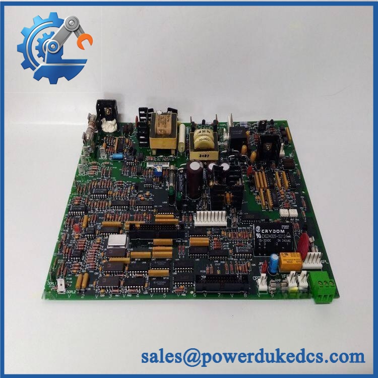
ABB 1MSC980119 REV.D
Module 4: Dynamic Emergency Swap & Configuration Guide
1. Pre-Swap Prep — Protect the Protection System
Place the rotating-machine protection system into the plant’s approved maintenance state and isolate all relevant AC/DC sources before opening the equipment. Verify absence of hazardous voltage with an approved meter. Record the complete identification 1MSC980119 REV.D / 1MRS050639 / RE_54 PS1_240V_MED, photograph connector positions, and document the existing power-supply alarms. Have an ESD wrist strap, insulated tools, calibrated meter, and the REM 543 wiring/service documentation ready.
2. Removal — Extract the Board Without Disturbing Adjacent Circuits
This is a board-level power-supply assembly, not a DIN-rail field device. The available dimensional record describes a compact PCB assembly of approximately 330 × 240 × 29 mm. After confirming isolation, disconnect the board’s plugs or harnesses one at a time and identify each connector by its terminal reference. Release the card-retention hardware, then withdraw the board straight from its mating interface. Avoid contact with exposed components and do not force a connector that has not fully released.
3. Installation & Configuration — Match the Power Board Exactly
Before installation, verify the replacement label against the removed board: 1MSC980119 REV.D, 1MRS050639, and RE_54 PS1_240V_MED. Fit the board in the same chassis position and restore all connectors according to the approved ABB drawing. The available product data identifies the output as 24 VDC / 1 A. Do not substitute another PS1 board merely because its connector arrangement appears similar; ABB lists multiple PS1 variants, including different supply configurations.
4. Power-On Self-Test (POST) — Confirm Stable DC Before Returning to Service
Re-energize under controlled conditions and check the protection terminal’s startup diagnostics. Verify the replacement supply produces the expected 24 VDC output under the permitted load and that the voltage remains stable after the system begins drawing current. Check for power-supply, processor, communication, or I/O alarms on the host terminal. A good POST is not just a successful power-up; the protection equipment must remain stable while all connected loads are restored.
Module 5: Quality Assurance & Testing SOP
Every ABB 1MSC980119 REV.D / 1MRS050639 should receive both board-level inspection and controlled functional testing before shipment.
- OEM anti-counterfeit visual inspection: Check ABB markings, 1MSC980119 identification, 1MRS050639 ordering number, REV.D revision, connector geometry, PCB workmanship, and component placement.
- Exact part-number verification: Confirm 1MSC980119 REV.D, 1MRS050639, and RE_54 PS1_240V_MED against the physical label and inspection record.
- Mechanical inspection: Examine PCB edges, mounting points, connector pins, fasteners, component condition, contamination, corrosion, cracked solder joints, and evidence of previous repair.
- Power-input verification: Verify the test setup against the approved REM 543 service documentation; do not infer the input specification from the
240Vdesignation alone. - Power-on self-test (POST): Energize the board in an approved compatible chassis or laboratory fixture and verify startup behavior and host-system diagnostic status.
- Output-voltage test: Measure the DC output and verify the specified 24 VDC / 1 A capability under the approved test conditions.
- Load test: Apply a controlled representative load and monitor output-voltage stability, abnormal heating, and any protection response.
- Ripple/noise check: Where the approved laboratory procedure specifies limits, measure DC ripple under both light and representative load conditions.
- I/O full-range simulation: Restore the board in a compatible host fixture and verify the power rail remains stable while connected processing, indication, communication, and I/O circuits are exercised.
- Thermal observation: Monitor the board during an extended powered test for abnormal temperature rise, hot spots, odor, fan abnormalities where applicable, or intermittent shutdown.
- Final QC record: Record serial/identification data, revision, measured output voltage, load current, test duration, diagnostic results, photographs, technician sign-off, and packaging condition.
Module 6: Maintenance & Reliability FAQ
1. Is ABB 1MSC980119 REV.D a direct drop-in replacement, or does it require a firmware flash?
This part is identified as a power-supply board, not a CPU or application processor. ABB’s product record identifies 1MRS050639 / PS1_240V_MED as a spare power-supply product, while other records associate it with the REM 543 rotating-machine terminal. A firmware flash would therefore not normally be the defining replacement task. The critical checks are exact part number, revision, connector arrangement, host chassis compatibility, and correct power configuration.
2. Is it safe to hot-swap this board while the system is running?
No, unless the specific host-equipment documentation explicitly permits live replacement. A power-supply board is connected directly to energized internal circuits. Shut down and isolate the equipment, discharge stored energy where applicable, and verify zero voltage before removing the card.
3. Will replacing 1MSC980119 REV.D cause my current program or settings to be lost?
The board itself is a power-supply assembly, so it is not the normal storage location for the host application’s program. However, the protection terminal’s configuration and protection settings can still be affected if the system loses power without proper backup procedures. Before replacement, save the applicable REM 543 configuration, protection settings, communication parameters, event records, and any calibration-related data according to the plant’s backup procedure.
4. What should I verify before commissioning the replacement?
Confirm 1MSC980119 REV.D, 1MRS050639, and RE_54 PS1_240V_MED. Then verify the host terminal model, chassis position, connector orientation, expected output voltage, and power demand. The available technical listing specifies 24 VDC / 1 A and approximately 0.44 kg net weight. Do not commission solely from the part-number match; check the actual output under representative load and confirm that the host protection terminal reports no power-related diagnostics.
5. What are the warranty terms if the unit fails after installation?
Warranty coverage should be defined on the quotation or sales order for the specific serialized unit. Preserve the incoming inspection record, board photographs, revision identification, measured 24 VDC output, load-test results, installation date, and host-system diagnostics. For a power-supply failure, those records make it much easier to separate an internal board fault from an overloaded or shorted downstream circuit.











 Start Chat


