

Description
- Brand: ABB
- Full Model Number: 216GD61A
- Associated Part References: HESG324430R9 / HESG324436M1/A / HESG324428 / HE502032-1730 / 216GD61A
- Series: RE.216 / REG216
- Lifecycle Status: Legacy protection-system spare; availability subject to physical inventory
- Core Function in System: Relay and optocoupler interface for binary trip, signaling, and input circuits
- Top 3 Hardcore Specs: 8 trip relays / 16 signaling relays / 16 optocoupler inputs
- Optocoupler Input Range: 82–312 VDC standard on 216GD61A; adaptable to 20–312 VDC with the specified series resistor arrangement
- System Compatibility: REG216 electronic protection system
- Condition & Lead Time: Physical condition, test status, and dispatch timing to be confirmed against available stock
ABB’s RE.216 documentation identifies 216GD61a as a relay-and-opto-coupler unit containing 16 optocoupler inputs, while the REG216 product description specifies eight trip relays, 16 signaling relays, and 16 optocouplers.
The supplied part-number family is also consistent with the documented ABB assembly. One technical procurement record identifies 216GD61A, HESG324436 M1/A, HESG324428 as the I/O assembly used in an ABB REG216 generator-protection application.
Module 3: Technical Intro & Downtime Impact
A failed binary interface in a generator or transformer protection system can prevent trip commands, status signals, or external protection inputs from reaching the REG216 electronics correctly. ABB’s 216GD61A is the relay-and-opto-coupler assembly used with the REG216 version, providing the interface between field binary signals and the protection system. The documented configuration includes 8 trip relays, 16 signaling relays, and 16 optocoupler inputs.
For maintenance planning, the most important specification is the field-interface architecture. On the documented 216GD61a, channels 1–16 are designed for 82–312 VDC; ABB’s manual also describes adaptation to other input voltages in the 20–312 VDC range through the specified series-resistor arrangement. The unit is supplied from 24 VDC, with provision for redundant supplies, and a 2 A fast fuse is specified for protection of that supply circuit. Those values are far more useful during an emergency swap than an assumed generic PLC specification.
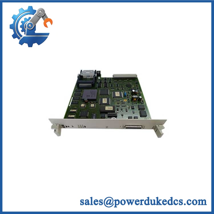
ABB 216GD61A HESG324430R9
Module 4: Dynamic Emergency Swap & Configuration Guide
1. Pre-Swap Prep
- Place the protection system under the approved maintenance/out-of-service procedure.
- Isolate the applicable auxiliary supply and field circuits according to the site protection procedure.
- Verify absence of hazardous voltage before accessing terminals.
- Photograph the existing 216GD61A, terminal wiring, connector positions, and any identification labels.
- Record whether the installation uses single or redundant auxiliary supplies.
2. Removal
- Access the rack or cabinet only after isolation has been verified.
- Label every field conductor before removal; do not rely on wire color alone.
- Disconnect the terminal wiring and associated interconnects using the documented terminal arrangement.
- Release the assembly from its rack/cabinet mounting points and withdraw it without stressing the PCB or relay terminals.
3. Installation & Configuration
- Verify the replacement markings against the failed assembly: 216GD61A, HESG324436M1/A, HESG324428, and the applicable manufacturing/reference numbers.
- Reinstall the unit in the same rack position and restore every field connection to its recorded terminal.
- Confirm the input-voltage arrangement before energizing. The ABB manual documents 82–312 VDC for the standard 216GD61a input channels and describes resistor-based adaptation for lower voltage applications.
- Verify the 24 VDC auxiliary supply and redundant-supply arrangement where fitted.
4. Power-On Self-Test (POST)
- Energize the protection rack according to the ABB commissioning sequence.
- Check the system’s diagnostic/status indications for supply, I/O, or internal communication faults.
- Exercise representative binary inputs and verify correct recognition by the protection system.
- Test representative relay outputs under an approved protection-test procedure; do not inject uncontrolled trip commands into energized plant equipment.
- Confirm that all required trip and alarm paths return to the expected healthy state.
The rack architecture matters here: ABB documents the 216GD61a as part of the compact system, installed with the 216MB66 or 216MB68 electronic equipment rack depending on single or redundant configuration.
Module 5: Quality Assurance & Testing SOP
Identity & Authenticity Control
- ABB identification and part-number verification
- Cross-check of 216GD61A / HESG324436M1/A / HESG324428
- OEM label and traceability inspection
- PCB, relay, optocoupler, connector, terminal, and mounting-hardware inspection
- Check for corrosion, contamination, cracked solder joints, damaged terminals, or unauthorized repair
Electrical Inspection
- Verify auxiliary supply path against the documented 24 VDC architecture
- Inspect the supply-protection arrangement, including the specified 2 A fast fuse where applicable
- Continuity testing of field-side wiring interfaces
- Insulation and grounding checks appropriate to the test setup
- Confirm input-voltage configuration against the installed application
Functional Test
- Controlled power-up
- Power-on self-test and diagnostic-status observation
- 16-channel optocoupler input simulation across the applicable voltage range
- Full-range binary I/O simulation using an approved test fixture
- Trip-relay output verification
- Signaling-relay output verification
- Input-to-status-path verification
- Fault/alarm response recording
ABB documentation confirms the 216GD61a architecture of 16 optocoupler inputs and the corresponding relay functions; these are therefore the critical points for pre-shipment functional screening rather than merely powering the PCB and declaring it operational.
Final QC Release
- Test results recorded against the unit’s serial/traceability information
- Configuration photographs retained
- Antistatic packaging
- Terminal/connector protection
- Shock-resistant outer packaging
- Final part-number and quantity verification
- QC technician release before shipment
Module 6: Maintenance & Reliability FAQ
Is ABB 216GD61A a direct drop-in replacement?
It can be a direct hardware replacement when the installed configuration and exact assembly references match. ABB documentation identifies 216GD61a as the relay-and-opto-coupler unit for , while field documentation can show associated references such as HESG324436M1/A and HESG324428. Match the complete identification before installation.
Is it safe to hot-swap the 216GD61A while the protection system is energized?
Do not assume hot-swapping is permissible. This assembly interfaces with protection-trip and field circuits, so removal can affect protection availability or create unintended signal states. Use the site’s approved protection-maintenance procedure and place the affected protection functions into the required safe maintenance condition before disconnecting the unit.
What input voltage does the 216GD61A support?
The ABB manual documents 82–312 VDC for the standard 216GD61a optocoupler channels. It also states that the inputs can be adapted for 20–312 VDC using the corresponding series resistor. Verify the actual resistor/configuration arrangement against the installed protection scheme before applying field voltage.
Will replacing the 216GD61A require a firmware flash?
The sources reviewed identify this as a hardware relay/opto-coupler interface assembly and do not establish a firmware-flashing requirement for the replacement. Preserve the existing configuration and test records, then verify I/O and protection behavior after installation rather than applying an undocumented software change.
What should be verified before ordering a replacement?
Match all available identifiers on the failed assembly, especially 216GD61A, HESG324436M1/A, and HESG324428. Then confirm the rack configuration, field-input voltage, trip-relay arrangement, and redundant auxiliary-supply setup. This prevents a visually similar board from being installed into a protection circuit with different field-interface requirements.











 Start Chat


