

Description
- Brand: ABB
- Full Model Number: KUC711AE101 / 3BHB004661R0101
- ABB Type Designation: KU C711 AE
- Product Type: Gate Unit Power Supply (GUSP)
- Lifecycle Status: ABB catalog-listed spare; exact installed converter generation requires verification
- Core Function in System: Power supply assembly for gate-unit electronics in high-power converter systems
- Top 3 Hardcore Specs: 24 VDC control supply context | 7 integrated subboards reported for the assembly | 279 × 191 × 203 mm
- Gate-Unit Architecture: KU C711 AE assembly with seven HB003688R0101 subboards according to current secondary product documentation
- Net Weight: 4.7 kg
- Primary Application: ABB ACS1000 medium-voltage drive installations
- Condition & Lead Time: New or verified surplus inventory subject to revision and configuration check; expedited dispatch for stocked units
ABB’s product record identifies 3BHB004661R0101 as KU C711 AE; GATE UNIT POWER S GUSP, with a net weight of 4.7 kg and dimensions of 279 × 191 × 203 mm. Secondary technical listings identify the KUC711AE101 variant with seven HB003688R0101 subboards and associate the assembly with ABB ACS1000 medium-voltage drives.
Module 3: Technical Intro & Downtime Impact
A failed gate-unit power assembly can disable a converter power section even when the upstream control system remains operational. In an ACS1000 installation, the gate-unit electronics are directly involved in controlling the high-power semiconductor switching stage. The ABB KUC711AE101 / 3BHB004661R0101 is identified by ABB as a KU C711 AE Gate Unit Power Supply (GUSP). Its role is therefore much closer to the power-electronics control chain than to a conventional low-voltage cabinet supply.
For MTTR planning, identification accuracy matters more than generic “gate driver” specifications. ABB’s catalog data gives a 279 mm × 191 mm × 203 mm envelope and 4.7 kg net weight, which provides a useful mechanical check before shipping a replacement to site. Secondary documentation describes the complete unit as containing seven HB003688R0101 subboards. Public sources retrieved here do not provide enough authoritative ABB documentation to assign a universal input/output voltage, gate-drive current, switching frequency, MTBF, or thermal specification to the exact KUC711AE101 assembly. Those numbers should come from the host converter drawing or OEM service documentation rather than being guessed.
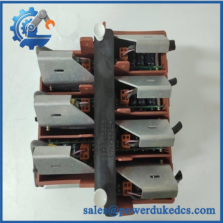
ABB 3BHB004661R0101 KUC711AE101
Module 4: Dynamic Emergency Swap & Configuration Guide
1. Pre-Swap Prep — Isolate the Converter and Map the Gate-Unit Connections
Start with the converter’s approved shutdown and LOTO procedure. This assembly belongs to a high-energy power-electronics system; verify the DC link and associated supply circuits have reached the safe state specified by the applicable ABB service procedure before opening the equipment.
Record the complete KUC711AE101 / 3BHB004661R0101 identification, serial number, cabinet location, cable routing, optical connections, control wiring, and subboard arrangement. Photograph the original assembly before removal. Do not rely on the model number alone when multiple gate-unit generations are installed at a plant.
2. Removal — Disconnect the Gate-Unit Assembly Without Stressing the Subboards
After electrical isolation has been verified, disconnect all control, supply, and optical interfaces according to the cabinet drawing. Protect fiber connectors from dust and mechanical impact; cap them where the maintenance procedure requires it.
Release the assembly’s retaining hardware and remove the KU C711 AE assembly as a complete unit. ABB’s published product dimensions are approximately 279 × 191 × 203 mm, with a 4.7 kg net weight, so support the assembly during removal rather than allowing its weight to load connected cables.
3. Installation & Configuration — Match the Complete Gate-Unit Assembly
Install the replacement 3BHB004661R0101 in the same cabinet position. Restore every electrical and optical connection according to the original drawing and verify that the replacement contains the correct gate-unit subassembly configuration.
Secondary product documentation states that this assembly contains seven HB003688R0101 subboards. Confirm the same subboard arrangement and any PCB revision or coating requirements before energization. Do not substitute an earlier or later KU C711 AE assembly based only on enclosure appearance; gate-unit generation and semiconductor compatibility must match the converter design.
4. Power-On Self-Test (POST) — Verify Gate-Unit Health Before Enabling the Power Stage
Restore the control supply under the approved commissioning procedure and observe all available gate-unit diagnostic indicators. Check for supply faults, communication faults, optical-link errors, or subboard-related alarms.
Before enabling high-power operation, verify that the converter recognizes the gate-unit assembly and that all expected gate-unit channels report healthy status. A controlled low-energy test or converter diagnostic sequence should be completed before applying normal load. A field note: an apparently healthy auxiliary supply does not prove that all seven internal gate-unit channels are functioning correctly.
Module 5: Quality Assurance & Testing SOP
Each available ABB KUC711AE101 / 3BHB004661R0101 should pass a documented hardware and functional QA sequence before shipment:
- OEM anti-counterfeit visual inspection — verify ABB markings, KU AE designation, 3BHB004661R0101 identification, labels, enclosure, connectors, optical interfaces, and manufacturing marks.
- Part-number reconciliation — compare the physical assembly against the customer’s ACS1000 or converter BOM and full ordering information.
- Mechanical inspection — verify the approximately 279 × 191 × 203 mm enclosure dimensions and mounting interfaces.
- Weight check — confirm the unit is consistent with ABB’s published 4.7 kg net weight before shipment.
- Subboard inventory check — verify the reported seven HB003688R0101 subboards are present where this assembly configuration is applicable.
- Connector inspection — examine electrical connectors, optical ports, terminal hardware, and board-edge interfaces for bent contacts, contamination, cracks, or heat damage.
- Insulation and grounding test — perform the applicable safety tests using the voltage and procedure specified for the actual converter assembly.
- Controlled power test — apply the appropriate auxiliary/control supply using a protected laboratory source and record voltage, current, and startup behavior.
- Power-on self-test (POST) checking for diagnostic LEDs — document every available Power, Fault, Ready, and communication indication during startup.
- Optical communication test — verify gate-control and diagnostic fiber links using a compatible ABB converter test environment where available.
- Gate-unit channel verification — exercise each supported gate-unit channel under a controlled, low-energy test setup and confirm expected diagnostic responses.
- Fault simulation — where the approved laboratory procedure allows it, simulate a controlled communication or gate-unit fault and verify that the converter reports the expected diagnostic condition.
- Thermal observation — operate the assembly under representative control activity and monitor abnormal heating, fan behavior, component noise, or diagnostic instability.
- Extended run test — maintain the unit under sustained control operation and record any intermittent optical, power, or subboard faults.
- Final QA record — retain nameplate photographs, serial-number data, subboard inventory, electrical measurements, diagnostic results, optical test results, and final packaging photographs.
ABB’s own product record is the strongest source for the type designation, dimensions, and weight. Supplier descriptions should not be used to substitute unverified electrical ratings for the actual converter documentation.
Module 6: Maintenance & Reliability FAQ
Is the ABB 3BHB004661R0101 a direct drop-in replacement, or does it require a firmware flash?
It is identified by ABB as a KU AE Gate Unit Power Supply, but direct replacement depends on the installed converter architecture, gate-unit generation, semiconductor type, subboard configuration, and control-system interfaces. The gate-unit assembly itself is hardware; the more important pre-installation check is matching the complete assembly configuration rather than assuming software flashing alone will make an incompatible unit usable.
Is it safe to hot-swap the while the system is running?
No. Do not assume live replacement is permitted. The unit operates within a high-power converter environment and can be connected to hazardous electrical energy and optical control circuits. Use the specific ABB maintenance procedure and plant LOTO process before disconnecting the assembly.
Will replacing the cause my current converter program to be lost?
The gate-unit power assembly is not the same as the main converter controller or application database. Replacing the physical gate-unit assembly should not normally erase the controller program. The replacement can still affect converter startup if the gate-unit hardware, optical configuration, or semiconductor interface is incorrect, so preserve the converter configuration and commissioning records before intervention.
What should I verify before ordering an emergency spare?
Verify , 3BHB004661R0101, the ABB type designation , host converter model, gate-unit generation, optical interface arrangement, and internal subboard configuration. ABB’s product data gives the type designation and physical envelope; secondary documentation reports seven HB003688R0101 subboards in the complete assembly. A clear photograph of the installed unit’s nameplate and connectors is strongly recommended.
What are the warranty terms if the gate-unit assembly fails after installation?
Warranty depends on the supplying party, stock condition, and purchase agreement. Confirm the warranty period, DOA policy, testing scope, and return procedure before shipment. Retain the pre-shipment QA record, serial-number photographs, subboard inventory, electrical test results, and commissioning diagnostics. Those records are important when separating a defective gate-unit assembly from an optical-link fault, downstream semiconductor issue, or converter-side control problem.











 Start Chat


