

Description
- Brand: ABB
- Full Model Number: UCD216A
- ABB Part Number: 3BHE027632R0101
- System/Series Family: ABB UNITROL / AC 800PEC-related control hardware
- Core Function: Digital I/O control interface for industrial power-control applications
- Top 3 Hardcore Specs: 16 digital I/O channels | 24 VDC signal level | 8 inputs + 8 outputs reported
- I/O Configuration: 8 digital inputs + 8 digital outputs
- Stock Status: New surplus, factory sealed, or fully tested refurbished subject to current inventory confirmation
The UCD216A 3BHE027632R0101 identification is supported by multiple secondary product records. One source describes it as a 16-channel digital I/O control board, while another associates the part with ABB power-control equipment. Public listings disagree on the exact product-family classification, so the installed equipment documentation and board nameplate should be used as the final compatibility reference.
Module 3: Technical Product Introduction
A failed digital I/O board can remove multiple field status and command signals from a power-control cabinet at once. The ABB UCD216A 3BHE027632R0101 is identified in available technical records as a digital I/O control board with 16 channels. One published specification describes an 8-input and 8-output arrangement, with digital signals associated with 24 VDC operation. That makes the complete part number important when sourcing a replacement; a board with the same physical format but a different I/O allocation is not an acceptable substitute.
The available specifications also indicate a compact control-board format rather than a large power-conversion assembly. One listing reports approximately 120 × 90 × 70 mm and 0.5 kg, while other sources provide different descriptions and dimensions. This discrepancy is significant. It means dimensions and weight should be treated as procurement references until the actual hardware revision is verified. For a replacement project, the more useful checks are I/O allocation, terminal arrangement, system family, firmware or configuration requirements, and the exact ABB ordering number.
Module 4: Application Scenarios & Field Realities
- In an ABB power-control cabinet, the UCD216A can be used where discrete equipment states and control commands need to be exchanged with the controller. When troubleshooting, check the field voltage at the terminal before condemning the I/O board; an open circuit or missing 24 VDC supply can produce symptoms that look like a failed module.
- For drive and converter control applications, digital feedback signals are often tied directly to permissives, interlocks, enable states, and equipment status. A replacement board should therefore be checked channel-by-channel against the original wiring schedule rather than installed solely from the part-number match.
- During a scheduled converter outage, retaining a correctly identified spare can shorten the hardware-replacement stage. Record the original connector positions and I/O assignments before removing the board, particularly when several similar control assemblies are installed side by side.
- Where the installation uses older ABB power-control hardware, verify the actual system architecture before assuming that every UCD216A listing describes the same application. Public records associate this part number with different ABB system descriptions, so the equipment nameplate and original documentation take precedence over generic catalog text.
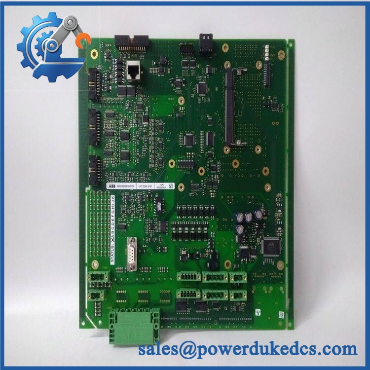
ABB 3BHE027632R0101 UCD216A
Module 5: Migration, Compatibility & Installation Traps
Replacement Matrix
| Replacement Type | Assessment | Engineering Requirement |
|---|---|---|
| Drop-in Replacement | Potentially applicable for an exact UCD216A 3BHE027632R0101 replacement | Match part number, revision, I/O arrangement, connector layout, and system application |
| Software Compatible | Configuration-dependent | Verify the controller configuration and any associated firmware requirements |
| Hardware Modification Required | Not normally expected for an exact same-part replacement | Do not substitute a different I/O board based only on channel count |
Field Traps — Watch Out
1. Conflicting product-family descriptions: Available sources identify 3BHE027632R0101 as a digital I/O board, while other listings describe the same number more generally as an ABB control board or associate it with other equipment families. Do not use a generic description as the basis for a retrofit. Confirm the original cabinet assembly and board marking first.
2. I/O polarity and channel assignment: A published description identifies 8 digital inputs and 8 digital outputs, with 24 VDC digital signals. Before energizing a replacement, compare every terminal against the original wiring diagram. Do not assume that a similarly numbered I/O board has identical input/output allocation.
3. Power isolation and ESD: Remove the relevant control power according to the site’s maintenance procedure before withdrawing the board. Use ESD protection when handling exposed electronics, and inspect connectors for bent contacts before reinsertion.
Module 6: Quality Assurance SOP
Before shipment, each ABB 3BHE027632R0101 should undergo a documented inspection sequence appropriate to the available test environment.
- Step 1 — Part-number verification: Record the ABB designation, 3BHE027632R0101 ordering number, revision markings, serial information, and all visible labels.
- Step 2 — OEM anti-counterfeit visual inspection: Examine ABB labels, PCB markings, connector construction, terminal identification, fasteners, component layout, and manufacturing identifiers. Photograph the nameplate and board markings.
- Step 3 — Physical condition inspection: Check for corrosion, contamination, cracked components, damaged terminals, bent connector pins, loose hardware, and evidence of previous repair or rework.
- Step 4 — Power-supply verification: Confirm the appropriate control voltage and test-fixture requirements before applying power. Do not energize the board based solely on a third-party catalog specification.
- Step 5 — Power-on self-test (POST): Where the correct ABB test environment is available, energize the board under controlled conditions and record ERR/RUN or equivalent diagnostic indications.
- Step 6 — Digital I/O verification: Apply representative digital input signals and verify the expected input-state response. Where the test fixture permits, exercise representative output channels and confirm correct switching behavior.
- Step 7 — Communication handshake verification: Where the complete controller or converter test environment is available, verify that the system recognizes the board and that the expected I/O status is exchanged correctly.
- Step 8 — Configuration cross-check: Confirm that the tested hardware corresponds to the customer’s requested 3BHE027632R0101 and the actual application family before packing.
- Step 9 — Final photographic record: Photograph the complete board, nameplate, connectors, revision markings, and packaging condition for the shipment file.
QA release criterion: No unexplained diagnostic alarm, physical damage, identification discrepancy, or failed I/O test should be accepted for shipment. If a complete system-level test cannot be performed, the inspection record should clearly distinguish board-level testing from full-system verification.











 Start Chat


