

Description
- Brand: ABB
- Full Model Number: 4LA41100102V1.2
- Designation: KB2 Display Unit
- Product Family: ABB KPM KB2
- Lifecycle Status: Legacy KPM spare; exact revision requires verification
- Core Function in System: Operator display and keyboard interface for ABB KPM KB2 sheet-break detection equipment
- Top 3 Hardcore Specs: 90–264 VAC supply | 50/60 Hz | 15 W typical consumption
- Measurement Interface: Fiber-optic connection to KB2 sensor head
- Digital Outputs: 2 dry-contact outputs for break and maintenance alarm
- Analog Outputs: Up to 3 optional 4–20 mA outputs
- Environmental Rating: IP66 / NEMA 4X reported for the electronics unit
- Operating Temperature: -10 to +60 °C for the electronics unit
- Physical Size: Approximately 323 × 237 × 70 mm; 3 kg for the electronics unit
- Condition & Lead Time: New or verified surplus inventory subject to revision and configuration confirmation; expedited dispatch for stocked units
ABB’s current KPM product notice explicitly identifies 4LA41100102V1.2 as the KB2 Display Unit. The KB2 documentation describes the unit as part of a fiber-optic sheet-break detection system, with display/keyboard operation and measurement data communication through the instrument electronics.
Module 3: Technical Intro & Downtime Impact
A sheet-break detector does not earn its keep by looking good on a cabinet door. Its value is measured in reaction time. When the display/control unit fails, operators can lose access to the KB2’s measurement display, configuration menus, alarm information, and local control functions, making a web-break event harder to diagnose and manage. The ABB 4LA41100102V1.2 KB2 Display Unit is specifically identified in ABB’s KPM product documentation as the KB2 display unit used with this instrumentation platform.
The supporting KB2 manual provides useful electrical and environmental figures: the applicable display unit is associated with a 90–264 VAC, 50/60 Hz supply and approximately 15 W consumption, while the electronics unit is specified at roughly 323 × 237 × 70 mm and 3 kg. The system uses fiber optics between the electronics/display assembly and the sensor head, keeping sensitive electronics away from the harsh machine environment. A response delay of 15 ms minimum is documented for break detection at the system level, although that should not be interpreted as the display unit’s standalone response time.
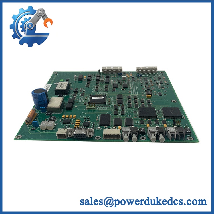
ABB 4LA41100102V1.2
Module 4: Dynamic Emergency Swap & Configuration Guide
1. Pre-Swap Prep — Preserve the Fiber and Configuration
At the machine, first isolate the KB2 according to the plant’s electrical maintenance procedure. Record the complete 4LA41100102V1.2 identification, supply wiring, fiber-optic cable routing, display settings, alarm configuration, analog-output assignments, and any RS-485 connection.
The KB2 system places the sensor head in a harsh process environment while the electronics remain outside the machine hood. ABB’s documentation warns against pulling the fiber-optic cable strongly. Photograph the fiber connector orientation before disconnecting it.
2. Removal — Disconnect the Display Unit From the Bottom Wiring Area
After power has been isolated, remove the lower cover as specified by the KB2 installation procedure. The electrical and fiber connections are located beneath the display-unit cover. Disconnect the AC supply, alarm/output wiring, analog connections if fitted, PC/RS-485 interface if used, and fiber-optic connection by the connector body.
Release the display unit from its mounting arrangement and remove it without placing stress on the fiber conduit. Inspect the connector area for contamination, loose terminals, moisture ingress, or mechanical damage.
3. Installation & Configuration — Match the Correct KB2 Display Variant
Install 4LA41100102V1.2 in the original enclosure position and restore the wiring exactly as documented. Confirm the replacement is the KB2 Display Unit rather than the similar KB2 24V Display Unit or the KB2 unit with an analog board. ABB’s current product notice lists these as separate product numbers, including 4LA41100102V1.2, 4LA41100200V1.1, and 4LA41100212V1.1.
Restore the original measurement configuration and alarm parameters. The KB2 manual uses a defined setup process in which the operator stores the web/paper level with SAMPLE, calculates the automatic limit, selects the appropriate detection signal, and enables the break alarm.
4. Power-On Self-Test (POST) — Verify Display, Fiber Signal, and Break Relay
Restore the specified AC supply and confirm that the display initializes normally and the keyboard responds to operator input. Verify that the sensor signal is being received through the fiber-optic path and that measured signal values remain stable.
Then perform a controlled break-detection test according to the KB2 commissioning procedure. Confirm that the break alarm relay operates as configured and that maintenance alarms are reported correctly. The documented KB2 configuration includes separate outputs for break and maintenance alarm functions.
Module 5: Quality Assurance & Testing SOP
Each available ABB 4LA41100102V1.2 / KB2 Display Unit should pass a controlled QA process before shipment:
- OEM anti-counterfeit visual inspection — verify ABB/KPM markings, 4LA41100102V1.2 identification, KB2 designation, display assembly, keyboard, enclosure, connectors, and manufacturing labels.
- Part-number reconciliation — compare the physical unit against 4LA41100102V1.2 and the customer’s KPM KB2 configuration.
- Variant verification — ensure it is the standard KB2 display unit and not 4LA41100200V1.1 or another 24 V/analog-board variant. ABB lists these separately.
- Mechanical inspection — check enclosure, mounting points, display window, keyboard, bottom cover, cable entries, and fiber connection.
- Power-on self-test (POST) checking for display and keyboard operation — apply a controlled 90–264 VAC input where applicable and verify normal startup, display operation, and keyboard response.
- Supply-current verification — document the measured current against the approximately 15 W system specification for the applicable KB2 electronics configuration.
- Fiber-optic communication test — connect the display unit to a known-good KB2 sensor/electronics assembly and verify stable optical signal transmission.
- Measurement simulation — introduce representative sensor signals and confirm correct display/update behavior.
- Break-detection test — simulate a valid web-break condition and verify the configured break indication and alarm response.
- Alarm-output test — verify the available relay outputs for break and maintenance conditions.
- I/O full-range simulation — where the installed variant includes analog outputs, verify the applicable 4–20 mA outputs across their operating range; ABB’s current connected-product notice confirms measurement data can be transmitted through 4–20 mA outputs and HART on supported KPM products.
- RS-485/PC interface test — verify the optional service/configuration interface where fitted.
- Extended run test — operate the unit under continuous measurement activity and monitor display stability, fiber communication, alarms, and abnormal temperature rise.
- Final QA record — retain product-label photographs, firmware/revision information where available, power measurements, fiber-test results, alarm tests, display/keyboard verification, and packaging photographs.
The KB2 system is designed to keep its electronics away from the harsh sensor environment; ABB notes that the sensor head can operate at elevated temperatures while the electronics unit remains outside the machine hood. That separation should be preserved during installation.
Module 6: Maintenance & Reliability FAQ
Is the ABB 4LA41100102V1.2 a direct drop-in replacement, or does it require a firmware flash?
It is identified by ABB as the KB2 Display Unit, but direct replacement depends on the existing KB2 configuration. ABB separately lists the standard KB2 display unit, 24 V display unit, and display unit with analog board. The display assembly itself is not normally treated like a PLC CPU requiring application firmware installation; configuration parameters still need to be verified after replacement.
Is it safe to hot-swap the KB2 display unit while the system is running?
Do not assume it is. The KB2 documentation specifies electrical wiring beneath the display-unit cover and provides both 110–230 VAC and 24 VDC system configurations depending on the model. Isolate the equipment under the applicable plant procedure before disconnecting the display unit.
Will replacing the KB2 display unit cause my current program or configuration to be lost?
The display unit is not the main process controller, but KB2 operating parameters and alarm settings still need to be preserved. Back up or record the detection mode, selected signal, detection limit, alarm limits, direction, light source, and other configured variables before replacement. The KB2 manual explicitly documents these configurable parameters.
What should I verify before ordering an emergency 4LA41100102V1.2 spare?
Verify the exact 4LA41100102V1.2 designation and compare it with the installed KB2 unit. Pay particular attention to the supply variant: ABB lists 4LA41100102V1.2 separately from the 4LA41100200V1.1 KB2 24V Display Unit and 4LA41100212V1.1 KB2 24V Display Unit with Analog Board. Also provide photographs of the label, connector area, and fiber connection.
What are the warranty terms if the display unit fails after installation?
Warranty depends on the supplying party and the purchase agreement. Confirm the warranty duration, DOA terms, testing scope, and return procedure before shipment. Keep the pre-shipment QA record and commissioning results, particularly the AC-input test, display/keyboard check, fiber communication test, and alarm-relay verification.











 Start Chat


