

Description
- Brand: ABB
- Full Model Number: 5SHY4045L0006
- ABB Product ID: 3BHB030310R0001
- Associated Gate Driver: GVC736CE101 / 3BHE039203R0101
- Lifecycle Status: Legacy / service spare; verify current production status before procurement
- Core Function in System: High-power IGCT switching device for medium-voltage converter and drive power stages
- Top 3 Hardcore Specs: 4500 V blocking voltage; up to 4000 A average on-state current under specified conditions; 70 kA surge current for 10 ms
- Switching Capability: Maximum specified di/dt ≥1000 A/µs; dv/dt ≥1000 V/µs; switching frequency up to 1600 Hz
- Cooling Arrangement: Dual-side cooling / compression-mounted heatsink installation
- Gross Weight: Approximately 3 kg
- Condition & Lead Time: Factory-sealed or professionally tested inventory subject to stock confirmation; expedited shipment available for shutdown-critical requirements
ABB’s product record identifies 3BHB030310R0001 as “4500V, 91mm, 5SHY 4045L0006; IGCT,” with a listed gross weight of 3 kg.
Module 3: Technical Intro & Downtime Impact
A failed IGCT can take an entire medium-voltage drive or converter out of service. The semiconductor sits directly in the high-energy switching path, so a short circuit, gate-control fault, or degraded device can trigger a converter trip and prevent the motor or process from restarting. ABB identifies 5SHY4045L0006 / 3BHB030310R0001 as a 4500 V IGCT intended for high-power converter applications. The associated GVC736CE101 / 3BHE039203R0101 is used as the gate-drive electronics in compatible assemblies.
From an MTTR perspective, the key advantage is electrical capacity rather than software configuration. The published product data specifies a 4500 V rating, up to 4000 A average current under the stated test conditions, and a 70 kA / 10 ms surge-current capability. Switching parameters are also significant: maximum specified di/dt ≥1000 A/µs, dv/dt ≥1000 V/µs, and switching frequency up to 1600 Hz. Replacement work therefore depends heavily on correct gate-driver matching, compression pressure, heatsink condition, thermal interface preparation, and the exact converter design. A visually identical IGCT is not an acceptable substitute without engineering verification.
Module 4: Dynamic Emergency Swap & Configuration Guide
1. Pre-Swap Prep — De-Energize the DC Link Completely
This is high-energy power-converter work. Apply the manufacturer’s shutdown sequence and plant LOTO procedure, isolate the incoming supply, discharge the DC link, and verify absence of hazardous voltage with an appropriately rated meter. Prepare an insulated torque wrench, ESD protection for the gate-control electronics, approved thermal-interface material, cleaning materials, and the converter’s assembly drawing. Do not begin mechanical removal until the DC bus has been proven discharged.
2. Removal — Release the Compression-Mounted Power Device
The 5SHY4045L0006 is not a DIN-rail or rack-slotted control device. It is a high-power IGCT intended for dual-side cooling / heatsink compression, so the mechanical stack-up matters. Photograph the existing semiconductor orientation, gate connection, heatsink arrangement, and thermal interface before loosening the assembly. Release the specified clamping mechanism evenly, disconnect the gate-drive connection, and remove the device without damaging the polished cooling surfaces or adjacent semiconductor hardware. The published ABB identification specifically calls out the 91 mm device designation.
3. Installation & Configuration — Match the Gate Driver and Clamp Geometry
Clean both heatsink faces according to the approved maintenance procedure and inspect them for scoring, contamination, or uneven contact. Position the replacement with the same electrical orientation and gate-terminal arrangement as the original device. Reconnect the compatible gate driver, identified here as GVC736CE101 / 3BHE039203R0101, only after confirming the converter’s exact schematic and revision. Apply the specified thermal interface and tighten the compression hardware using the OEM-defined sequence and torque/pressure requirements. Never estimate clamp force by feel — insufficient or uneven pressure can produce excessive thermal resistance and localized heating.
The associated ABB records identify GVC736CE101 and 3BHE039203R0101 with this IGCT combination, but procurement records should still be checked against the actual converter BOM before substitution.
4. Power-On Self-Test — Validate Gate Pulses Before Applying Full Power
With the converter still in a controlled test condition, inspect the gate-driver diagnostics first. Confirm the expected gate-drive status, fiber-optic communication where fitted, and absence of semiconductor fault indications. Perform the manufacturer’s low-energy or test-mode checks before reconnecting the full DC-link operating circuit. Where the maintenance procedure permits, verify gate pulse timing and protection feedback with the approved test equipment. Only after the device passes the static checks should the converter be energized progressively under controlled load.
A gate-drive fault that appears immediately after installation should be treated as a configuration or interface problem until proven otherwise — not as evidence that the replacement IGCT itself is defective.
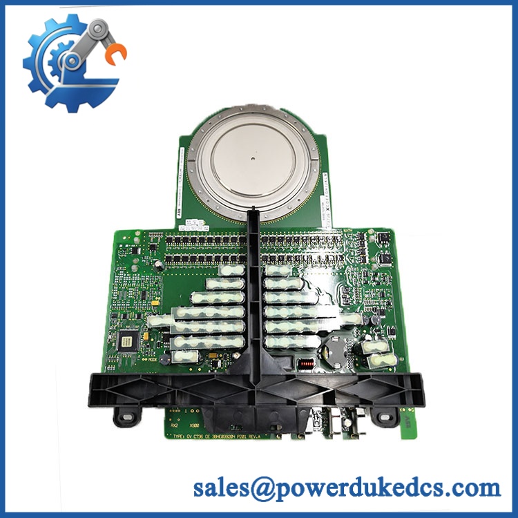
ABB 5SHY4045L0006
Module 5: Quality Assurance & Testing SOP
Each ABB 5SHY4045L0006 / 3BHB030310R0001 should undergo semiconductor-specific inspection before shipment.
- OEM anti-counterfeit visual inspection: Verify ABB markings, 5SHY4045L0006 designation, 3BHB030310R0001 product ID, label quality, housing geometry, gate terminals, and manufacturing traceability.
- Part-number verification: Match the complete product identification against the customer’s failed component and approved drive BOM.
- Mechanical inspection: Check ceramic surfaces, terminals, contact faces, mounting interfaces, and insulating components for cracks, chips, contamination, oxidation, or impact damage.
- Electrical isolation check: Perform controlled insulation and isolation measurements using a procedure appropriate to the device and test equipment. Do not exceed the manufacturer’s permitted test conditions.
- Static semiconductor verification: Conduct approved forward-blocking and gate-related checks using a dedicated high-power semiconductor test setup.
- Gate-drive compatibility test: Where the associated GVC736CE101 / 3BHE039203R0101 is supplied, verify the gate-control interface and diagnostic response as a matched assembly.
- Gate trigger verification: Confirm the applicable trigger characteristics. Secondary published data lists a gate trigger requirement of approximately ≤3.0 V / ≤300 mA for this device family; verify against the exact ABB technical documentation before using those values as a production acceptance limit.
- Thermal-interface inspection: Confirm flatness and cleanliness of both cooling surfaces and verify the required compression arrangement.
- Power-stage simulation: Where the laboratory setup permits, test the switching path under controlled electrical conditions and monitor abnormal leakage, heating, or protection trips.
- Thermal observation: Monitor temperature rise during an extended controlled test — especially important when the intended cabinet has older cooling hardware or restricted airflow.
- Final QC record: Record product ID, serial/traceability information, test equipment, measured values, inspection photographs, test date, and QC release status before packaging.
ABB’s published product record lists the device as a 4500 V IGCT and classifies it as a spare part, with a gross weight of 3 kg.
Module 6: Maintenance & Reliability FAQ
Is this a direct drop-in replacement, or does it require a firmware flash?
There is no firmware flash for the IGCT itself. The critical compatibility checks are electrical rating, physical geometry, gate-drive compatibility, converter topology, heatsink arrangement, and the exact hardware revision. The listed 5SHY4045L0006 / 3BHB030310R0001 is specifically identified by ABB as a 4500 V, 91 mm IGCT.
Is it safe to hot-swap the 5SHY4045L0006 while the system is running?
Absolutely not. This is a high-voltage, high-current power semiconductor installed directly in the converter power path. The DC link and associated circuits must be isolated, discharged, and proven de-energized before mechanical work begins. Follow the exact drive maintenance procedure and plant LOTO requirements.
Will replacing this IGCT cause my current program to be lost?
Replacing the power semiconductor does not normally erase the drive application, parameters, or controller program. Those reside in the control system rather than inside the IGCT. Even so, capture the drive parameter set, control firmware revision, fault history, and converter configuration before shutdown. After replacement, validate the gate-driver interface and protection settings before returning the drive to production.
What should I verify before ordering against GVC736CE101?
Verify the complete hardware combination rather than ordering by the gate-driver designation alone:
5SHY4045L0006 → 3BHB030310R0001 → / 3BHE039203R0101
The ABB product record confirms 3BHB030310R0001 as the product ID for the 4500 V, 91 mm, 5SHY4045L0006 IGCT. The customer’s converter BOM should determine whether the listed gate-drive assembly is the correct companion hardware.
What are the warranty terms if the unit fails after installation?
The warranty should be tied to the specific shipped device and its recorded condition at dispatch. Retain the product identification photographs, incoming inspection record, electrical test results, installation record, compression/thermal-interface verification, and commissioning measurements. Those records are important when separating a semiconductor failure from excessive clamping force, inadequate cooling, gate-drive faults, or an upstream converter fault.











 Start Chat


