

Description
- Brand: ABB
- Full Model Number: 81EU01
- Ordering Number: GJR2391500R1210
- System/Series Family: ABB PROCONTROL P / P14
- Core Function: Universal input module for acquiring process and field signals
- Top 3 Hardcore Specs: 16 functional units | +24 V supply | Analog and binary input capability
- Signal Types: Binary contacts, analog current/voltage, transmitter signals
- Stock Status: New surplus, factory sealed, or fully tested refurbished subject to current inventory confirmation
ABB 81EU01 is identified in multiple technical listings as a universal input module, with GJR2391500R1210 associated as its product/order reference. Published descriptions identify it with the ABB PROCONTROL P family, while some sources specifically identify PROCONTROL P14.
Module 3: Technical Product Introduction
A failed input module in an ABB PROCONTROL installation can remove an entire group of field signals from the controller, even when the sensors and transmitters themselves remain healthy. The ABB 81EU01 GJR2391500R1210 is a universal input module intended to interface field instrumentation with the control system. Published technical descriptions identify 16 functional units, allowing different input functions to be handled within the same module rather than requiring a separate board for every signal category.
The useful engineering feature is signal flexibility. Available documentation describes support for binary contacts together with analog current and voltage signals, including transmitter-type inputs. One published specification lists a +24 V supply and a base current requirement of approximately 140 mA, with additional consumption depending on the active functional units. Treat those values as reference data until the exact hardware revision is confirmed against the original documentation—PROCONTROL installations can differ by configuration.
Module 4: Application Scenarios & Field Realities
- In boiler and turbine control cabinets, the 81EU01 can serve as the interface for process measurements and discrete field contacts. During troubleshooting, verify the signal at the field terminal first; replacing the input board will not correct an open transmitter loop or failed instrument.
- For process transmitters using current or voltage signals, the universal-input architecture is useful because multiple signal types can be handled within the same module family. Confirm the configured input function before moving a transmitter connection to a replacement channel.
- During an outage on an older PROCONTROL installation, a correctly identified 81EU01 spare can shorten the hardware-replacement stage. Photograph the original terminal arrangement and record channel assignments before removing the defective module.
- Where binary and analog signals share the same control cabinet, channel configuration becomes particularly important. The physical module may look correct while the configured functional-unit assignment is wrong. That is a commissioning issue, not a cosmetic one.
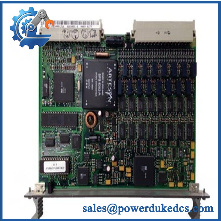
- ABB 81EU01 GJR2391500R1210
Module 5: Migration, Compatibility & Installation Traps
Replacement Matrix
| Replacement Type | Assessment | Engineering Requirement |
|---|---|---|
| Drop-in Replacement | Yes, when replacing the same 81EU01 / GJR2391500R1210 configuration | Verify exact ordering number, revision, channel configuration, and rack position |
| Software Compatible | Configuration-dependent | Confirm functional-unit assignments and the installed PROCONTROL application |
| Hardware Modification Required | Not normally required for an exact same-part replacement | Do not substitute another input module based only on channel count |
Field Traps — Watch Out
1. Do not confuse channel count with channel function: Published descriptions identify 16 functional units, but the module’s universal-input capability means the actual signal configuration matters. A replacement must be configured for the same field-signal functions as the original.
2. Supply and transmitter-current checks: One published specification identifies +24 V supply and approximately 140 mA base consumption. Where transmitters are powered through the module, additional current requirements can depend on the active functional-unit configuration. Verify the cabinet’s actual wiring and power budget before energizing the replacement.
3. Part-number suffix matters: The references 81EU01, 81EU01-R1210, and GJR2391500R1210 appear across published records. Do not treat a visually similar 81EU01 variant as automatically interchangeable. Match the complete identification printed on the existing module.
Module 6: Quality Assurance SOP
Before shipment, each ABB 81EU01 unit should pass a controlled inspection sequence appropriate to the available test equipment.
- Step 1 — Part-number verification: Record ABB 81EU01, , revision information, serial number, and all visible identification labels.
- Step 2 — OEM anti-counterfeit visual inspection: Inspect ABB label construction, printing, PCB markings, connectors, terminal blocks, fasteners, and manufacturing identifiers. Photograph the nameplate for the inspection record.
- Step 3 — Physical condition inspection: Check the PCB and housing for corrosion, contamination, cracked components, bent terminals, damaged connectors, loose hardware, and signs of previous repair.
- Step 4 — Power-supply inspection: Verify the applicable +24 V supply requirement against the intended test setup before energizing the module. Do not apply power based solely on a catalog listing.
- Step 5 — Power-on self-test (POST): Energize the module under controlled conditions where the correct PROCONTROL test environment is available. Record ERR/RUN or equivalent status indicators and any diagnostic response.
- Step 6 — Input-channel verification: Test representative binary and analog input paths according to the available test fixture. Confirm that expected signal states or measured values are correctly recognized.
- Step 7 — Communication handshake verification: Where the test environment supports the complete PROCONTROL architecture, verify module-to-controller communication and confirm that the expected module status is recognized by the control system.
- Step 8 — Final identification check: Compare the tested unit against the customer’s requested reference before packing.
- Step 9 — Photographic QA record: Photograph the complete module, nameplate, connectors, visible revision markings, and final packaging condition.
QA release criterion: No unexplained diagnostic fault, identification discrepancy, physical damage, or failed input-channel test should be accepted for shipment. If a full PROCONTROL system test is unavailable, the inspection record should clearly distinguish visual/electrical testing from complete system-level testing.











 Start Chat


