

Description
- ABB AIM0006 | Isolated Transducer Input Unit For Power Electronic Control Cabinet
Product Core Brief
- Model: AIM0006
- ABB Part Code: 2RCA021397A0001 (suffix variants: F / K / L / M)
- Brand: ABB
- Series: PCS6000 / ACS6000 Medium Voltage Drive Spare Series
- Core Function: Collect current transformer and voltage transformer signals plus binary status signals for drive main control unit
- Product Type: CT/VT Analog & Binary Input Interface PCB Module
- Key Specs: 3 CT inputs + earth fault CT input; 5 VT inputs; 4 binary input channels; onboard signal conditioning circuit
- Condition: New surplus stock, factory hardware testing completed
- Lifecycle Notice: ⚠️ Discontinued original production, limited remaining inventory
Product Introduction
Key Technical Specifications
| Parameter Item | Technical Data |
|---|---|
| Full Identifier | AIM0006 / 2RCA021397A0001 |
| Signal Channels | 3 phase CT + SEF earth fault CT; 5 VT; 4 binary inputs |
| Application Platform | ABB PCS6000, ACS6000 medium voltage converters |
| Installation Form | Plug-in card inside control rack, rear backplane connection |
| Signal Processing | Onboard low-pass filter and galvanic isolation circuit |
| Operating Supply | 24 V DC control power |
| Operating Temperature | -20 °C ~ +55 °C |
| Storage Temperature | -40 °C ~ +85 °C |
| Protection Standard | IP00 (must be mounted inside closed electrical cabinet) |
| Compatible Backplane | Standard slot for PCS6000 control unit frame |
| Net Weight | Approx 0.32 kg |
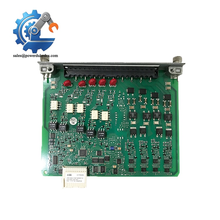
ABB AIM0006
Installation & Configuration Guide
Pre-Installation Preparation (12 mins)
Implement lockout-tagout procedures. Cut off medium voltage primary power and 24 V control supply for the converter. Keep waiting for minimum 10 minutes to discharge DC bus capacitors.
ESD wrist strap, PH1 screwdriver, digital multimeter, mobile phone for wiring photo backup.
Capture clear photos of all front terminal wiring and backplane connector position. Record existing CT polarity arrangement before disconnection. CT secondary circuits must be short-circuited before unplugging any wiring.
Old Module Removal (10 mins)
Step 2: Label each VT, CT and binary input wire one by one. Disconnect front terminal wiring gently.
Step 3: Release locking screws on both sides of the module frame, pull the board straight out horizontally. Do not twist the PCB.
Step 4: Inspect rack backplane pins for bending or oxidation. Clear accumulated dust with dry compressed air.
New Module Installation (15 mins)
Step 2: Verify full part number AIM0006 and suffix code. Different suffix versions have slightly adjusted terminal definitions.
Step 3: Insert the PCB evenly into the rack slot and tighten side fixing screws.
Step 4: Restore wiring strictly following photographed records, double-check CT polarity and shorting links are removed after wiring completes.
All CT shorting links removed ✅
CT wiring polarity consistent with original layout ✅
All terminals fully tightened ✅
Module fixed parallel inside rack frame ✅
Power-On & Commissioning (25 mins)
Step 1: Restore control power first, observe module onboard indicator status.
Step 2: Launch drive commissioning software and check real-time CT/VT measured values.
Step 3: Verify binary input status matches actual auxiliary switch positions.
Step 4: Run converter no-load test, monitor balance of three-phase measured currents and voltages.
Step 5: Maintain continuous observation for 30 minutes, confirm no abnormal signal drift or diagnostic alarms.
Step 6: Update equipment maintenance log with module serial number and replacement date.
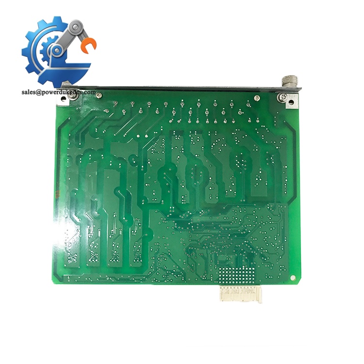
ABB AIM0006
Quality Inspection Process
- Incoming Visual Inspection
Check PCB silkscreen model number, no scratch marks, no traces of repair, burnt tracks or component deformation.
- Power-Up Basic Test
Supply rated 24 V DC power, confirm no internal short circuit, indicator lamps respond normally.
- Channel Continuity Test
Check all CT/VT and binary input channels for open or short circuit defects.
- Signal Simulation Test
Input simulated secondary signals to validate acquisition circuit performance.
- Data Filing
Record serial number, hardware revision and test date for complete traceability.
- Final Packaging
Seal module inside anti-static bag, fill bubble cushion and attach QC passed shipping label.
Field Replacement Pitfall Guide
Multiple 2RCA021397A0001 suffix variants exist. Using mismatched variants leads to inconsistent terminal assignment and signal loss. Confirm full code before ordering.
Always install shorting links on CT terminals before disconnecting cables. Open CT secondary circuit generates hazardous high voltage.
Unprotected handling causes invisible partial channel damage. Intermittent measurement errors often emerge weeks after commissioning.
Reversed CT wiring results in wrong power factor calculation and incorrect protection operation. Polarity must be cross-checked after rewiring.
Route CT/VT shielded cables separately from high-power power cables. Parallel wiring creates signal noise under full converter load.
Pulling the module at an angle will bend backplane pins, leading to intermittent communication and signal faults.
Frequently Asked Questions (FAQ)
-
Which drive systems support AIM0006?
It is designed for ABB PCS6000 and ACS6000 series medium voltage converters, serving as measurement signal interface inside control racks.
-
Can AIM0006 support hot swapping?
Hot swap operation is forbidden. All rack power must be fully disconnected before module removal or installation.
-
Does extra parameter configuration need to be done after replacement?
No dedicated software settings for the board itself. You only need to confirm CT ratio parameters inside the main drive control program remain unchanged.
-
Can this module process primary voltage signals directly?
No. It only accepts standard secondary signals from CT and VT instrument transformers. Direct high voltage connection will destroy the PCB instantly.
-
Is AIM0006 still under active production by ABB?
Original manufacturing has been discontinued. Available units come from remaining new surplus inventory. Last-time-buy orders are no longer open.
-
What warranty applies for stocked modules?
All available boards carry a 12-month warranty. Damage caused by miswiring, overvoltage surge and ESD abuse will not be covered.
-
Can binary input channels be redefined freely?
Channel functions are fixed by PCB hardware layout. No flexible software remapping for binary input terminals.











 Start Chat


