

Description
- Brand: ABB
- Full Model Number: COM0023
- Product Family: ABB Relion 615 Series / compatible protection IED platforms
- Product Type: Optional rear communication module
- Core Function in System: Adds serial and optical communication interfaces to compatible ABB protection relays
- COM1 Interface: EIA-232 or EIA-485, via X6
- COM2 Interface: EIA-485 via X5 or optical ST via X12
- Port Architecture: 2 independent communication ports
- 2-Wire Operation: COM1 + COM2
- 4-Wire Operation: COM2
- Fiber Interface: Optical ST
- Configuration: Jumper-selected communication mode
- Default COM1 Mode: EIA-232
- Condition & Lead Time: Stock condition subject to inspection; emergency dispatch available subject to order confirmation
ABB’s technical documentation identifies COM0023 as an optional communication module for the 615-series protection IEDs. It supports EIA-232/EIA-485 on X6, EIA-485 on X5, and optical ST on X12. Two independent communication ports are available, with the exact combination determined by the connector and jumper configuration.
Module 3: Technical Intro & Downtime Impact
A communication-module failure can leave an otherwise healthy protection relay unable to exchange serial data with a legacy RTU, SCADA gateway, local engineering workstation, or protection-communication network. The resulting alarm may look like a wider relay failure because supervisory data disappears even though protection functions remain active. ABB COM0023 is an optional communication board used with compatible Relion 615-series devices, providing configurable serial and optical interfaces. ABB documents two independent communication ports, allowing combinations of EIA-232, EIA-485 2-wire, EIA-485 4-wire, and optical ST communication.
For MTTR, the important parameter is interface compatibility rather than processor performance. COM1 uses X6 and can be configured for EIA-232 or through jumpers X19, X20, X21, and X26; ABB states that these jumpers are set for EIA-232 by default. COM2 can use or X12 for optical ST. In a replacement event, preserving those jumper positions can eliminate hours of serial-link troubleshooting after the relay has been returned to service.
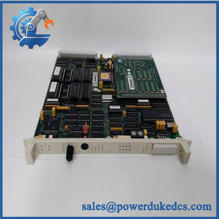
ABB COM0023
Module 4: Dynamic Emergency Swap & Configuration Guide
1. Pre-Swap Prep — Record the Communication Topology
Place the protection IED in the plant’s approved maintenance condition and follow the site’s switching procedure. Before touching the relay, photograph the COM0023 board, connector assignments, jumper positions, fiber path, serial wiring, and the existing communication diagnostics. Record whether COM1 is operating as or , whether COM2 uses X5 or X12, and the connected equipment on each link. Have an ESD strap, suitable screwdrivers, labeling materials, approved service documentation, and a laptop or serial diagnostic tool available.
2. Removal — Release the Rear Communication Board Carefully
COM0023 is a rear communication module, not a DIN-rail field device. De-energize the applicable relay assembly when the host equipment procedure requires it, then remove the retaining hardware and release the module from its connector interface. Disconnect the serial cable and optical connection without bending the fiber or forcing the PCB. Keep the original board beside the replacement so the connector layout and jumper configuration can be compared directly.
3. Installation & Configuration — Reproduce the Existing Port Mode
Install the replacement COM0023 in the same rear communication position and secure the retaining hardware. Restore X6, X5, and X12 connections according to the original installation record. The critical step is the jumper configuration: ABB specifies X19, X20, X21, and X26 for selecting COM1 between and . The documented default is , so a site using must have those jumpers restored to the site’s recorded positions.
For COM2, verify whether the installation uses through X5 or optical ST through X12. A two-wire arrangement can use and independently; when only one 4-wire serial port is configured, ABB designates it as . The optical ST connection uses as described in the ABB documentation.
4. Power-On Self-Test (POST) — Confirm Link Activity, Not Just Power
Restore power and check the host relay for communication-related diagnostics. Then verify the communication LEDs. ABB identifies RX/TX indicators on X6 for and RX/TX indicators on X5/X12 for , with the exact interpretation depending on the configured interface. The I-B indicator on X5 provides IRIG-B activity information.
After local link activity is confirmed, test the actual connected device: poll the serial slave, verify the engineering connection, or confirm the protection-communication path with the approved commissioning procedure. For fiber, inspect the ST connectors and verify receive/transmit activity. A powered communication card with no RX/TX activity is not a completed repair.
Module 5: Quality Assurance & Testing SOP
Every should receive board-level inspection followed by interface-specific functional testing.
- OEM anti-counterfeit visual inspection: Check ABB markings, PCB identification, connector geometry, component placement, solder quality, and board revision.
- Exact configuration inspection: Record the installed revision and compare jumper positions with the customer’s original configuration.
- Mechanical inspection: Examine mounting hardware, PCB edges, connector pins, ST optical interface, and signs of corrosion, impact, contamination, or unauthorized repair.
- electrical-interface test: Verify operation and operation using the approved test fixture, including the applicable jumper configuration.
- serial test: Verify 2-wire communication through X5 and, where supported by the test fixture, 4-wire operation.
- Optical test: Use an approved ST fiber test path to confirm optical transmit and receive operation through X12.
- LED diagnostic test: Check and RX/TX activity indicators while passing controlled communication traffic. ABB documents these LED assignments for .
- IRIG-B verification: Where the host installation uses the X5 timing interface, verify the applicable I-B activity indication.
- Communication stress check: Exercise repeated polling or message exchange and monitor for CRC errors, framing errors, dropped packets, or intermittent link loss.
- Host-IED test: Install the board in a compatible ABB protection relay test assembly and confirm that the host recognizes and communicates through the configured interface.
- Final QC record: Record module identification, board revision, jumper state, interface tested, baud/configuration settings where applicable, measured test results, LED activity, test duration, technician sign-off, and packaging condition.
Module 6: Maintenance & Reliability FAQ
1. Is ABB a direct drop-in replacement, or does it require a firmware flash?
is an optional communication module, so the primary replacement concern is hardware and configuration compatibility rather than firmware flashing. The host relay must support the option, and the replacement should reproduce the original connector and jumper configuration. ABB documents for compatible 615-series protection IEDs with , , and optical ST communication functions.
2. Is it safe to hot-swap while the system is running?
Do not assume hot-swap capability. Whether the rear communication board may be removed under power depends on the exact host IED and its service procedure. For a field replacement, use the approved outage or maintenance procedure, control ESD, and isolate the equipment whenever the manufacturer documentation does not explicitly permit live replacement.
3. Will replacing cause my current communication settings to be lost?
The communication hardware replacement itself does not mean the relay’s application configuration is erased, but the physical interface mode can change if the replacement’s jumpers do not match the original board. Before removal, record X19/X20/X21/X26 positions, serial-port assignments, communication parameters, and the interface selection. ABB specifically identifies those jumpers as the / selection mechanism.
4. What should I verify before commissioning the replacement?
Verify the exact host relay family first. Then match , at X5 or X12, and the jumper configuration. Confirm whether the plant uses , 2-wire, 4-wire, or optical ST. Finally, perform an end-to-end communication test rather than stopping after confirming that the RX/TX indicators respond. ABB’s documentation confirms the supported port combinations and LED assignments.
5. What are the warranty terms if the unit fails after installation?
Warranty coverage should be stated in the quotation or sales order for the specific serialized unit. Retain the incoming inspection report, jumper photographs, connector photographs, communication test results, host-relay model, and post-installation diagnostic records. For communication hardware, those records are particularly useful because cable, termination, addressing, baud-rate, and grounding problems can produce symptoms that closely resemble a defective board.











 Start Chat


