

Description
- Brand: ABB
- Full Model Number: CSA463AE
- ABB Part Number: HIEE400103R0001
- Lifecycle Status: Legacy / replacement-stock sourcing
- Core Function in System: Excitation-system control and signal-processing board
- Top 3 Hardcore Specs: HIEE400103R0001 identification; analog/digital signal processing; ABB excitation-system application
- Condition & Lead Time: Condition and actual stock quantity confirmed before dispatch; emergency replacement shipment available
Module 3: Technical Intro & Downtime Impact
A failed excitation control board can move a generator problem from a board-level fault to a production-level event.
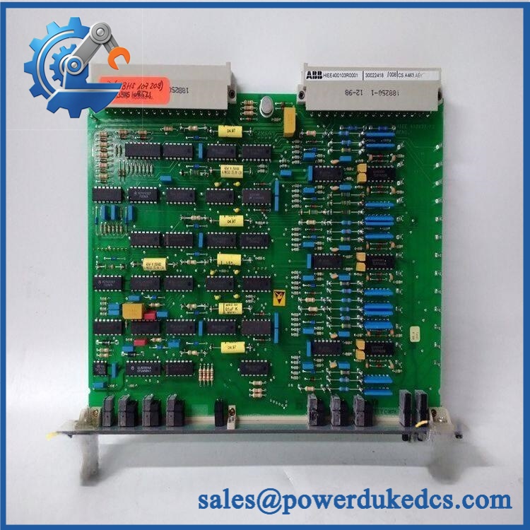
ABB CSA463AE HIEE400103R0001
Its role centers on processing measurement signals and participating in the control path that regulates generator excitation. The board should therefore be treated as a functional control-system spare, not as a generic PCB.
For MTTR, the important advantage is hardware-level interchangeability within the correct cabinet and revision. Current references identify HIEE400103R0001 as the associated part number for CSA463AE and describe the board as an excitation control/interface board. Some supplier literature states a 24 VDC supply and analog signal-processing capability, but ABB-specific electrical limits should be verified against the installed excitation-system documentation before energization. (Field note: board-level compatibility can depend on hardware revision and the exact excitation rack.)
Module 4: Dynamic Emergency Swap & Configuration Guide
1. Pre-Swap Prep — Isolate the Excitation Cabinet
Place the generator/excitation system in the plant’s approved maintenance state. Apply LOTO and verify that stored electrical energy has been discharged before accessing the electronics. Photograph the CSA463AE nameplate, connector locations, jumper settings, board revision, and cable routing. Record the complete HIEE400103R0001 identification before removing anything.
2. Removal — Release the Rack-Mounted PCB Carefully
After confirming a de-energized condition, disconnect external harnesses using their identification points rather than pulling the wires. Release the PCB retaining hardware or extraction mechanism used by the installed excitation rack, then withdraw the board evenly from the backplane connector. Keep the removed board in an ESD-safe package for failure analysis.
3. Installation & Configuration — Match the Original Hardware State
Compare the replacement’s part number, revision markings, connector arrangement, and configurable hardware against the failed board. Seat the CSA463AE squarely into the rack and secure its retaining hardware before reconnecting field wiring. Restore every jumper, termination, and selector to the documented original position. Do not assume that two boards carrying the CSA463AE marking are interchangeable when the complete ABB ordering code or revision differs.
4. Power-On Self-Test — Verify Regulation Hardware Before Loading the Generator
Restore auxiliary power according to the manufacturer’s commissioning sequence. Watch the available power, status, and fault indications during initialization. Verify that the excitation controller recognizes the board and that no immediate board, communication, sensing, or protection alarm appears. Before returning the generator to service, perform the site’s controlled excitation functional test and confirm correct voltage-regulation response.
Module 5: Quality Assurance & Testing SOP
Our pre-shipment QA process treats ABB CSA463AE HIEE400103R0001 as a safety- and availability-relevant excitation control spare.
- OEM Anti-Counterfeit Visual Inspection: Compare ABB markings, board identification, label construction, connector geometry, PCB finish, revision markings, and serial information against available reference material.
- Part-Number Verification: Confirm both CSA463AE and before the unit enters final inspection.
- PCB Mechanical Inspection: Examine edge connectors, mounting hardware, terminal interfaces, solder joints, visible components, and the PCB for corrosion, impact damage, contamination, or bent contacts.
- Power-On Self-Test (POST): Apply the approved auxiliary supply on an appropriate excitation-system test arrangement and monitor startup status and fault indications.
- Supply Verification: Where the applicable hardware documentation specifies 24 VDC auxiliary power, verify supply polarity and measured voltage before applying power. Supplier technical references identify 24 VDC for this board, but the installed system documentation remains authoritative.
- Signal Simulation: Inject controlled voltage/current measurement signals into the applicable test interface and verify the board’s signal-processing response.
- Control-Loop Simulation: Exercise representative excitation control conditions and monitor the board’s response through the available test interface.
- Fault Testing: Apply controlled diagnostic conditions where the test rack permits them and verify expected fault recognition.
- Final QC Record: Record serial number, exact ABB part number, hardware revision, test date, measured results, inspector, and packaging condition.
Module 6: Maintenance & Reliability FAQ
Q1. Is ABB a direct drop-in replacement, or does it require a firmware flash?
Do not classify it as a guaranteed drop-in replacement from the short model number alone. Current references identify with , but board revision and the specific excitation-system hardware must also match. Verify the existing board revision and system documentation before installation.
Q2. Is it safe to hot-swap the while the system is running?
Do not hot-swap this board unless the exact ABB excitation-system documentation explicitly authorizes that procedure. Generator excitation equipment can involve hazardous stored energy and consequences from incorrect field control. Use LOTO, verify de-energization, and follow the equipment-specific maintenance procedure.
Q3. Will replacing the cause my current excitation settings to be lost?
A PCB replacement should not be treated as a substitute for a configuration backup. Before removal, record the controller configuration, jumper/selector positions, calibration information, alarm settings, and any stored commissioning parameters applicable to the excitation system. Retain the original board until the replacement has completed functional testing.
Q4. What should I verify before ordering an ABB spare?
Verify , , hardware revision, connector arrangement, excitation-system model, and cabinet/rack compatibility. One supplier listing identifies the board as compatible with ABB excitation equipment, while other current references describe it more generally as a power-electronics control/interface board. The complete installed-system identification should take precedence over generic catalog descriptions.
Q5. What are the warranty terms if the replacement fails after installation?
Warranty depends on the supplier’s written purchase terms and the tested condition of the particular unit. Keep the serial number, incoming inspection report, pre-shipment test record, installation date, alarm history, and commissioning results. Those records are essential when separating a board defect from wiring, power-supply, configuration, or excitation-system faults.











 Start Chat


