

Description
Module 2: The 10-Second Buyer’s Brief
- Brand: ABB
- Full Model Number: DSAO 110 / 57120001-AT
- System/Series Family: ABB Advant OCS / S100 I/O
- Core Function: 4-channel isolated analog output for voltage and current control signals
- Top 3 Hardcore Specs: 4 channels; 0–10 V / 0–20 mA; 0.05% accuracy
- Isolation: Isolated analog outputs
- Exchange Number: EXC57120001-AT
- Dimensions: 209.7 × 225 × 18 mm
- Net Weight: 0.595 kg
- Stock Status: New Surplus / Factory-Sealed or Fully Tested Refurbished subject to actual inventory condition
ABB documentation identifies DSAO 110 as a four-output S100 analog output board. The published technical data specifies 0–10 V and 0–20 mA signals with 0.05% accuracy and isolation.
Module 3: Technical Product Introduction
When an ABB Advant S100 analog output channel fails, the problem is not simply loss of a single signal. Affected control loops can drive valves, actuators, dampers, or other final-control elements to an incorrect state. The ABB DSAO 110 57120001-AT provides four isolated analog output channels for this architecture, with selectable 0–10 V and 0–20 mA signal ranges. Its 0.05% accuracy is suited to control applications where the output value itself matters—not merely whether an output is present. ABB lists DSAO 110 within the S100 I/O family used with Advant control systems.
For replacement planning, the useful numbers are straightforward: 4 channels, 0–10 V, 0–20 mA, 0.05% accuracy, isolated outputs, 209.7 × 225 × 18 mm, and approximately 0.595 kg net weight. There is no credible basis for assigning a specific scan time or output update rate without the applicable system configuration documentation. That distinction matters when troubleshooting an installed system. The DSAO 110 is also an older S100 design; ABB identifies DSAO 120A + DSTA 171 as the replacement combination for DSAO 110 + DSTA 160, with wire reconnection required.
Module 4: Application Scenarios & Field Realities
- Refinery control loops: Where a DSAO channel drives a control valve positioner, a failed output can leave the loop without a valid manipulated variable. The four-channel DSAO 110 provides isolated voltage or current outputs for these analog control paths. Verify whether the existing field device expects 0–10 V or 0–20 mA before reconnecting the replacement.
- Process temperature regulation: In a heater or furnace control cabinet, the analog output may command a valve position or another final-control element. A 0–20 mA output is particularly useful where the control architecture has been engineered around current transmission. Check the cabinet drawings rather than assuming every channel uses the same signal range.
- Motor and actuator control: A DSAO 110 channel can form part of an analog command path to equipment requiring a proportional reference. If only one channel has failed, channel-by-channel verification is preferable to replacing the entire I/O assembly without diagnosis.
- Legacy Advant installations: The bigger concern is often hardware continuity rather than nominal electrical specification. DSAO 110 belongs to the S100 I/O family, and ABB’s system documentation lists it as a four-output analog board. For an aging installation, inspect the associated termination assembly and wiring before ordering a replacement board.
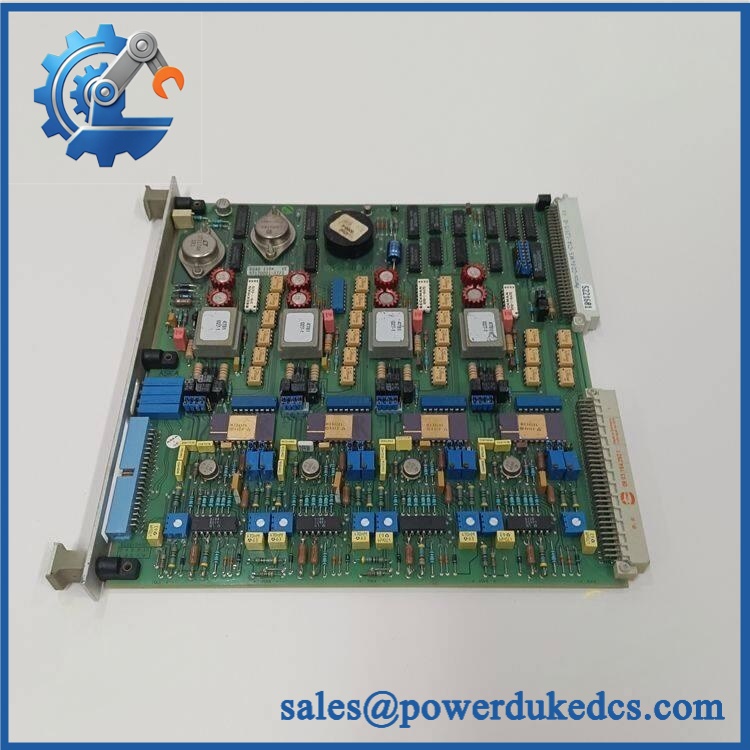
ABB DSAO110 57120001
Module 5: Migration, Compatibility & Installation Traps
Replacement Matrix
| Replacement Case | Classification | Engineering Requirement |
|---|---|---|
| Existing DSAO 110 57120001-AT replaced with the same part number | Drop-in Replacement | Verify hardware revision, termination arrangement, and system configuration |
| DSAO 120A + DSTA 171 replacing DSAO 110 + DSTA 160 | Hardware Modification Required | Wire reconnection is required |
| Different analog output board substituted without approved system configuration | Not a direct replacement | Confirm I/O configuration and termination compatibility first |
ABB specifically states that DSAO 120A + DSTA 171 replaces DSAO 110 + DSTA 160, but also notes that reconnection of the wiring is required. Treat this as a migration, not a simple board swap.
Field Traps — Watch Out
1. Voltage/current signal mismatch:
The DSAO 110 supports 0–10 V and 0–20 mA outputs. Do not assume that the field cable connected to a failed module can be moved to another output configuration without checking the loop design. Confirm the channel assignment, signal type, polarity, and receiving-device specification against the cabinet drawings.
2. Termination-unit compatibility:
The DSAO 110 is associated with the DSTA 160, while ABB identifies DSTA 171 with the DSAO 120A replacement combination. Do not install the newer board and retain the old termination arrangement on the assumption that the connector interface is equivalent. ABB explicitly calls for wire reconnection during this replacement.
Installation note: Power down the relevant I/O section according to the site’s maintenance procedure before removing the board. Protect the exposed electronics from ESD during handling.
Module 6: Quality Assurance SOP
For surplus DSAO 110 inventory, the correct approach is to verify the physical hardware first and electrical operation second. A useful pre-shipment procedure should include:
- Part-number verification: Confirm the ABB designation DSAO 110 and product identification 57120001-AT / EXC57120001-AT against the sales record and physical label.
- OEM anti-counterfeit visual inspection: Examine ABB labeling, PCB markings, connector construction, date/revision markings, screws, coating, and board workmanship for inconsistencies.
- Mechanical inspection: Check the PCB, front plate, connector areas, mounting points, and housing for cracks, deformation, corrosion, or impact damage.
- Power-on self-test (POST): Energize the module using an appropriate test setup and record the status of ERR/RUN LEDs and any diagnostic indication available from the host system.
- Channel verification: Test all four analog output channels individually rather than validating only one representative channel.
- Signal-range verification: Verify the applicable 0–10 V and 0–20 mA output behavior against the required test conditions.
- Accuracy check: Compare measured output against the test reference and record the result. The published module specification identifies 0.05% accuracy.
- Isolation verification: Check the output channels and relevant isolation points according to the applicable test procedure.
- Communication handshake verification: Install the module in a compatible test rack/system and confirm that the host recognizes the I/O module without configuration or communication faults.
- Final inspection: Photograph the tested unit, label, serial/date information where available, and packaging before shipment.
- Traceability: Retain the test record with the unit’s part number and condition classification so the shipped module can be matched to its inspection data.
For this part, the most important distinction is between identity verification and functional verification. A module can carry the correct part number and still require electrical testing before it is released for a critical spare-parts application.











 Start Chat


