

Description
Module 2: The 10-Second Buyer’s Brief
- Brand: ABB
- Full Model Number: DSBB175
- Part Number: 57310256-CC
- System/Series Family: ABB Advant Master / MXB Bus System
- Core Function: MXB bus backplane for interconnecting compatible control-system modules
- Top 3 Hardcore Specs: Bus backplane | MXB bus architecture | ABB Advant Master compatibility
- Physical Reference: Approx. 0.5–0.6 kg reported
- Stock Status: New surplus / condition to be confirmed per available unit
Public product references identify DSBB175 as an ABB bus backplane and associate part number 57310256-CC with the MXB bus backplane. Reported physical specifications vary between sources, so shipment-specific weight should be confirmed rather than treated as an absolute datasheet value.
Module 3: Technical Product Introduction
A failed backplane can stop more than one field module from communicating correctly. The ABB DSBB175 is a bus backplane associated with the ABB Advant Master control architecture, providing the physical interconnection required by compatible modules on the MXB bus. Available references identify it specifically as an MXB bus backplane, with 57310256-CC associated with the DSBB175 designation.
The key value here is architectural compatibility, not processor performance. DSBB175 does not function like a CPU, I/O processor, or communications controller; it provides the passive bus infrastructure that allows the intended modules to interface through the rack/backplane arrangement. Reported net weights range around 0.5–0.6 kg, although packaging and source-specific measurements differ. —Confirm the exact revision and board marking before replacing a failed unit.
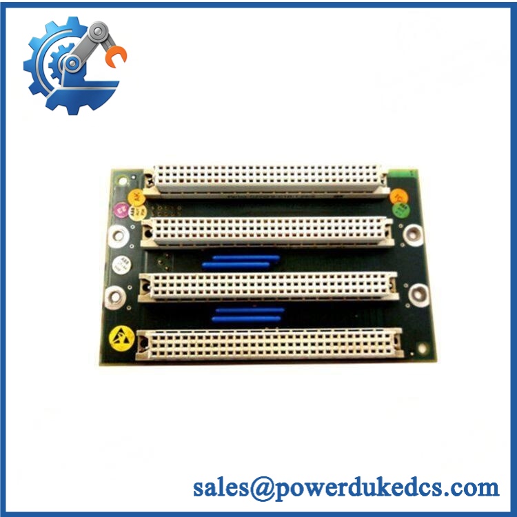
ABB DSBB175
Module 4: Application Scenarios & Field Realities
- During an Advant Master maintenance outage, DSBB175 is relevant when the fault follows the physical bus/backplane rather than an individual controller or I/O module. A replacement board should be matched by the complete part identification, not by model number alone.
- For legacy MXB rack restoration, the backplane provides the physical module interconnection required by the installed architecture. If several modules show communication symptoms simultaneously, inspect connectors, bus contacts, mounting condition, and the backplane before replacing multiple electronic modules.
- When restoring a discontinued control cabinet, DSBB175 can be useful as a direct hardware replacement candidate where the existing installation uses the corresponding MXB configuration. The exact board revision matters.
- In preventive spare-parts planning, keeping the correct backplane revision available can reduce troubleshooting time when an intermittent bus fault appears. A visual inspection alone is not enough; connector condition and electrical continuity should also be checked.
Module 5: Migration, Compatibility & Installation Traps
Replacement Matrix
| Replacement Type | DSBB175 Assessment |
|---|---|
| Drop-in Replacement | Potentially yes — only when the existing unit is the same DSBB175 / 57310256-CC configuration |
| Software Compatible | Not the primary issue; this is a backplane rather than a software-defined CPU or communication module |
| Hardware Modification Required | No modification expected for a correctly matched replacement; verify mechanical and connector compatibility first |
Field Traps — Watch Out
Part-number mismatch: DSBB175 appears in references alongside different suffix/revision designations, including DSBB175B / 57310256-ER. Do not treat these as automatically interchangeable simply because the base model is similar.
Connector and bus damage: Before installing the replacement, inspect the mating connectors for bent contacts, oxidation, contamination, or mechanical stress. A new backplane will not correct a damaged connector or an underlying rack alignment problem.
Power isolation: Disconnect the applicable cabinet power and follow the site’s ESD procedure before removing the board. Backplane work is not the place to rely on a live-rack installation unless the equipment documentation explicitly permits it.
Module 6: Quality Assurance SOP
Before shipment, the DSBB175 should pass a documented inspection sequence:
- OEM identification inspection — Verify ABB markings, model designation, board labels, revision information, and the complete part number against the ordered specification.
- Anti-counterfeit visual inspection — Check label quality, PCB workmanship, connector construction, markings, and signs of rework or unauthorized component replacement.
- Physical inspection — Examine the PCB, mounting points, connectors, solder joints, and contact surfaces for corrosion, impact, contamination, or deformation.
- Part-number verification — Confirm DSBB175 and, where applicable, 57310256-CC against the purchase requirement before packing.
- Electrical/continuity verification — Check accessible bus and power paths according to the applicable test procedure without applying unsupported test voltages.
- System-level verification where test equipment is available — Install the board into a compatible test assembly and verify module interconnection and bus continuity.
- Communication handshake verification — Where the complete compatible rack/test system permits it, confirm that the connected control modules establish the expected bus communication.
- Final visual inspection and packaging — Record the unit condition, identification labels, test result, and packaging condition before dispatch.
QA note: DSBB175 is a backplane, so a conventional CPU-style POST with RUN/ERR LEDs may not apply to the board itself. Any LED or diagnostic verification should therefore be performed at the corresponding controller/module level rather than falsely claiming that DSBB175 has CPU POST indicators.











 Start Chat


