

Description
- Brand: ABB
- Full Model Number: DSPU131
- ABB Part Number: 3BSE000355R1
- Product Type: MA200 Interface Board
- System Family: ABB Advant Master Process Control System
- Lifecycle Status: Legacy installed-base control-system component
- Core Function in System: MA200 interface within an AT-Bus control-system architecture
- Top 3 Hardcore Specs: MA200 interface; AT-Bus compatible; full-length 334.6 mm board
- Product Length: 334.6 mm
- Product Height: 121.9 mm
- Product Width: 21 mm
- Net Weight: 0.42 kg
- Country of Origin: Sweden / Germany listed in ABB product data
- HS Code: 85389091
- RoHS Status: Exempted under the applicable Advant Master declaration
- Condition & Lead Time: Tested inventory or factory-sealed stock; emergency dispatch subject to confirmed availability
ABB product data identifies DSPU 131 / 3BSE000355R1 specifically as an MA200 Interface Board, with technical information describing it as an interface board for AT-Bus with dimensions of 334.6 × 121.9 × 21 mm and a net weight of 0.42 kg. ABB also lists it as a control-system accessory associated with the Advant Master Process Control System.
Module 3: Technical Intro & Downtime Impact
A failed MA200 interface can interrupt communication between a control-system section and the associated bus architecture, producing multiple downstream symptoms at once. Instead of one failed field signal, engineers may see missing data, communication alarms, unavailable subsystem information, or a controller section that cannot complete its expected initialization. ABB DSPU131 3BSE000355R1 is specifically identified as an MA200 Interface Board for AT-Bus, making exact hardware identification essential when repairing an older Advant Master installation.
The verified physical data is equally important during an emergency swap. The board measures 334.6 mm in length, 121.9 mm in height, and 21 mm in width, with a documented net weight of 0.42 kg. Public sources that add processor speed, memory capacity, or modern network protocols are not consistent with ABB’s product identification, so those figures should not be presented as confirmed specifications for this part. For MTTR reduction, focus on the exact part number, AT-Bus position, connector arrangement, cabinet drawing, and post-installation communication testing. —a correct mechanical fit does not by itself prove bus compatibility.
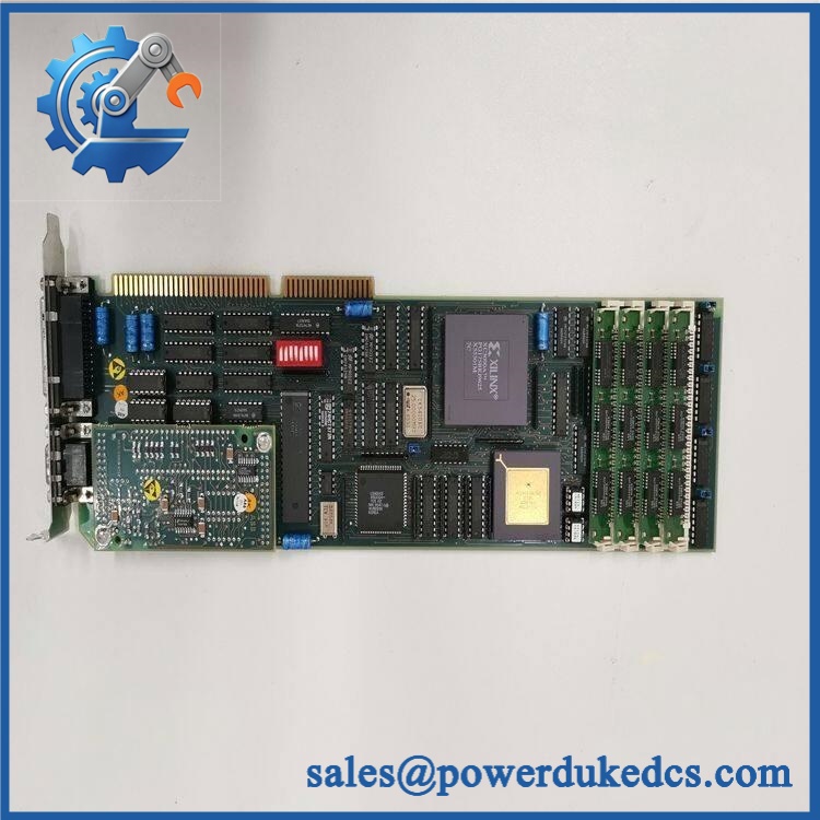
ABB DSPU131 3BSE000355R1
Module 4: Dynamic Emergency Swap & Configuration Guide
1. Pre-Swap Prep — map the bus position before isolation
Place the affected Advant Master control section in the plant-approved maintenance state and follow the site’s LOTO procedure where required. Photograph the DSPU131 nameplate, board orientation, connector locations, bus position, status indicators, and adjacent interface hardware. Record 3BSE000355R1, the installed hardware revision, cabinet slot, associated segment, and available diagnostic information. Use ESD protection and a calibrated meter appropriate to the cabinet supply.
2. Removal — preserve the AT-Bus connection geometry
After approved isolation, label every connector and cable before disconnecting it. Record each connection against the cabinet drawing rather than relying on position memory. Release the DSPU131 from its installed board carrier or backplane arrangement and withdraw it without flexing the long PCB. At 334.6 mm in length, the board is substantially longer than many newer automation cards, so support it during removal. Inspect the mating contacts and card guides for contamination, corrosion, or mechanical damage.
3. Installation & Configuration — reproduce the original architecture
Install the replacement DSPU131 3BSE000355R1 in the original AT-Bus position and secure the retaining hardware. Reconnect all interfaces exactly as shown in the original cabinet documentation. Confirm that the replacement is the same interface-board designation and hardware revision required by the installation. Restore the controller-side configuration associated with the segment, including the correct node or bus assignment where applicable. Do not substitute a different DSPU-series processor or interface board simply because the connector pattern appears similar.
4. Power-On Self-Test (POST) — prove bus communication before returning control
Restore system power according to the approved startup procedure. Observe all available status and diagnostic indications during initialization. Confirm that the host system recognizes the DSPU131 and that the /AT-Bus communication path returns to its expected state. Check representative process data, status information, alarms, and communication diagnostics across the affected section. Where practical, compare the recovered data against the pre-failure baseline before returning the control section to automatic operation.
Module 5: Quality Assurance & Testing SOP
The should undergo physical, interface, and bus-level verification before release.
- OEM Anti-Counterfeit Visual Inspection: Verify ABB markings, , 3BSE000355R1, PCB layout, connector arrangement, component placement, and board revision.
- Serial and Identity Traceability: Photograph the complete product marking and record serial, revision, and manufacturing identifiers where available.
- Mechanical Inspection: Check the full-length PCB, mounting points, board guides, connectors, retaining hardware, and edge contacts.
- Dimensional Verification: Confirm approximately 334.6 × 121.9 × 21 mm against the documented ABB dimensions.
- Weight Verification: Record approximately 0.42 kg net weight where warehouse asset control requires it.
- Power Verification: Apply the verified cabinet supply under controlled laboratory conditions and record startup behavior.
- Power-On Self-Test (POST): Check all available RUN, status, warning, and fault indicators during initialization.
- AT-Bus Interface Test: Verify electrical continuity and bus-interface behavior against the approved test fixture.
- Communication Test: Confirm valid communication between the interface board and a known-good test environment.
- Data Exchange Test: Exercise representative status and process-data transfers and confirm correct receipt at the host system.
- Bus Fault Simulation: Where the test fixture permits, interrupt the communication path and verify expected diagnostic behavior.
- Controller Recognition Test: Confirm that the host Advant Master environment identifies the installed without persistent hardware alarms.
- Extended Powered Test: Monitor for intermittent bus faults, unexpected resets, communication dropouts, or abnormal thermal behavior.
- Final QC Record: Document part number, revision, dimensions, communication-test results, diagnostic observations, photographs, and QC approval.
ABB’s product identification is clear on the component’s role: DSPU 131 Interface Board for AT-Bus. That is the appropriate baseline for laboratory acceptance; unsupported processor-speed, memory, or protocol claims should not replace the actual system documentation.
Module 6: Maintenance & Reliability FAQ
1. Is the 3BSE000355R1 a direct drop-in replacement, or does it require a firmware flash?
It is an interface board for AT-Bus, rather than a modern standalone controller. The primary checks are the exact / 3BSE000355R1 identification, hardware revision, bus position, connector arrangement, and Advant Master configuration. A generic firmware-flash requirement is not established by ABB’s available product identification for this exact part.
2. Is it safe to hot-swap this interface board while the system is running?
Do not assume live removal is permitted. The is part of a legacy AT-Bus control architecture, and the safe replacement procedure depends on the specific cabinet and bus implementation. Unless the applicable Advant Master maintenance documentation explicitly permits energized replacement, isolate the relevant system before removing the board.
3. Will replacing this interface board cause my current control program to be lost?
Replacing the does not by itself mean replacing the main control application. The main concern is restoring the correct bus and hardware configuration. Back up the Advant Master configuration, assignments, communication parameters, application data, and cabinet documentation before intervention.
4. What should I verify after installing the replacement?
Check the board’s startup diagnostics first. Then verify AT-Bus communication, data exchange, controller recognition, process values, alarms, and status information. A normal power indication is not enough; the recovered interface must exchange valid data with the host control system.
5. What are the warranty terms if the unit fails post-installation?
Warranty coverage should be tied to the supplied serial number and documented stock condition. Hardware defects should be distinguished from failures caused by incorrect installation, damaged backplane contacts, electrical faults, ESD, configuration errors, or failures elsewhere on the AT-Bus. The exact warranty period and return procedure should be stated on the quotation before purchase.











 Start Chat


