

Description
Module 1: High-Converting SEO Title Matrix
- Brand: ABB
- Full Model Number: GD9924BE/V2
- Ordering Number: HIEE401091R0002
- Lifecycle Status: Legacy installed-base component; exact system compatibility should be verified before replacement
- Core Function in System: Digital I/O interface / control and switching signal interface
- Top 3 Hardcore Specs: 32 digital inputs; 32 digital outputs; 24 VDC digital I/O signaling
- Input Range: 0–30 VDC reported
- Output Range: 0–30 VDC reported
- Input Current: ≤7 mA reported
- Output Current: ≤500 mA reported
- Response Time: ≤1 ms reported for both digital input and output
- Condition & Lead Time: Tested inventory or factory-sealed stock; emergency dispatch subject to confirmed stock
The strongest matching records identify GD9924BE/V2 with HIEE401091R0002 and describe it as an ABB analog/digital I/O card, with one detailed listing specifying 32 digital inputs and 32 digital outputs, 24 VDC signaling, and response times of ≤1 ms.
Module 3: Technical Intro & Downtime Impact
When a discrete I/O interface fails, the problem can appear much larger than a single circuit board. Start commands may disappear, interlocks can remain false, valve or contactor feedback may be lost, and a controller can generate secondary alarms across an entire control section. The ABB GD9924BE/V2 HIEE401091R0002 is identified in available technical records as an I/O/control board used for digital signal interfacing, making accurate channel identification critical during an outage.
For the matching GD9924BE/V2 records, the published electrical data includes 32 digital inputs, 32 digital outputs, 0–30 VDC I/O range, ≤7 mA input current, and ≤500 mA output current, with a reported response time of ≤1 ms. Another field listing associates the same part number with ABB SFC/SRM trigger applications, so the exact cabinet function should be confirmed from the original drawing and installed board label rather than inferred solely from the model number.
Module 4: Dynamic Emergency Swap & Configuration Guide
1. Pre-Swap Prep — establish the channel map before disconnecting anything
Place the affected control system in the plant-approved maintenance state and follow LOTO requirements. Photograph the GD9924BE/V2 nameplate, terminal strips, connector positions, LED states, and adjacent boards. Record every active I/O channel and its field-device designation. Use an ESD wrist strap and a calibrated multimeter. Before removing the card, verify the replacement carries HIEE401091R0002 and the same hardware/version marking.
2. Removal — preserve every field connection reference
After the approved isolation procedure, remove the field-side connectors or terminal plugs systematically, tagging each one by channel group rather than relying on memory. Release the board from its rack, card guide, or retaining hardware and withdraw it without twisting the PCB. Inspect the mating connector for bent contacts, contamination, or heat damage. A replacement card cannot correct a damaged backplane connection.
3. Installation & Configuration — reproduce the original I/O assignment
Install the replacement into the same slot and secure its mechanical retainers. Reconnect each signal group according to the cabinet wiring diagram. Verify 24 VDC polarity and field voltage before energizing outputs. Pay particular attention to any output circuits driving relays, solenoids, or contactors; the published field specification of ≤500 mA per digital output should not be treated as permission to exceed the actual system drawing or load specification.
4. Power-On Self-Test (POST) — prove the channels under controlled conditions
Restore control power and inspect all available status/fault indicators. Confirm the host controller recognizes the I/O hardware without persistent diagnostics. Exercise representative digital inputs from field simulation equipment, then command outputs into a safe test state and verify the corresponding terminal voltage and feedback. Complete a channel-by-channel functional check before returning interlocks, motors, valves, or other controlled equipment to automatic operation.
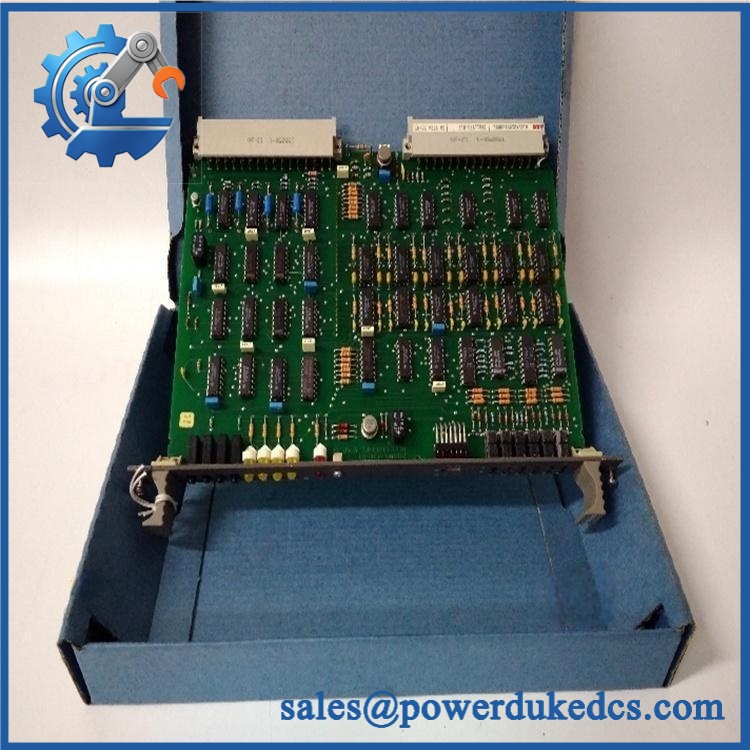
ABB GD9924BE/V2 HIEE401091R0002
Module 5: Quality Assurance & Testing SOP
The replacement should leave the warehouse with a traceable electrical test record, not just a visual inspection.
- OEM Anti-Counterfeit Visual Inspection: Compare ABB markings, GD9924BE/V2 designation, HIEE401091R0002 ordering number, PCB construction, connectors, labels, and component placement against verified reference hardware.
- Serial/Identity Traceability: Photograph the nameplate and record model, ordering number, hardware revision, and serial information.
- Mechanical Inspection: Check PCB edges, connector housings, mounting points, terminal interfaces, and card-retention hardware.
- Power Verification: Apply the documented control supply under current-limited laboratory conditions and record startup behavior.
- Power-On Self-Test (POST): Check all available RUN, status, and fault LEDs during initialization.
- Digital Input Simulation: Apply controlled input voltages across the documented operating range and verify every available input channel changes state correctly.
- Digital Output Test: Command every output channel through its defined states while measuring terminal voltage and confirming proper switching behavior.
- Full-Range I/O Simulation: Test representative or all channels according to the customer’s required acceptance level, including transition timing and state recovery.
- Load Verification: Where applicable, test outputs with a controlled representative load rather than connecting an uncontrolled field actuator directly.
- Channel Isolation Check: Confirm that activation of one digital channel does not create an unintended state change on neighboring channels.
- Extended Run Test: Keep the board energized long enough to expose intermittent startup faults, unstable signals, or abnormal thermal behavior.
- Final QC Record: Release the unit only after the serial number, measured results, firmware/hardware information, photographs, and inspection sign-off are attached to the shipment record.
Published technical records for this exact ordering number specify 32 DI + 32 DO, 24 VDC digital signaling, and ≤1 ms response time, providing useful baseline acceptance criteria; however, the customer’s approved system drawing remains the controlling reference for actual field limits.
Module 6: Maintenance & Reliability FAQ
1. Is the /V2 HIEE401091R0002 a direct drop-in replacement, or does it require a firmware flash?
Usually, the primary concern with this type of legacy I/O card is hardware and configuration matching, not a generic firmware upgrade. Verify the exact ordering number, hardware revision, rack/slot location, I/O mapping, and host-system configuration before installation. Public technical records identify with /V2, but descriptions of its system role vary substantially, so the installed cabinet documentation should control the final compatibility decision.
2. Is it safe to hot-swap this module while the system is running?
Do not assume so. The available evidence does not establish a universal hot-swap procedure for /V2. Treat the replacement as a de-energized intervention unless the specific ABB system documentation explicitly authorizes live insertion/removal for that rack and configuration.
3. Will replacing this I/O card cause my current program to be lost?
Replacing an I/O interface card normally does not constitute replacing the controller’s application program. The risk is different: incorrect channel mapping, configuration mismatch, or an incompatible hardware revision can prevent the controller from correctly using the replacement. Back up the complete controller project, hardware configuration, I/O database, alarm mapping, and cabinet drawings before intervention.
4. What should I test after installing the replacement?
Check supply voltage first. Then confirm controller recognition, diagnostic status, every required digital input, every required output, interlock behavior, field feedback, and alarm recovery. For output circuits, verify the actual connected load and protection rather than relying only on an LED or software status.
5. What are the warranty terms if the unit fails post-installation?
The warranty should be tied to the supplied serial number and documented condition, whether factory-sealed or tested inventory. Coverage should address hardware failure under specified operating conditions while excluding wiring errors, overvoltage, ESD damage, unauthorized modification, and incorrect system configuration. The exact warranty duration and return procedure should be confirmed on the commercial quotation.











 Start Chat


