

Description
- Brand: ABB
- Full Model Number: GFD233A103
- ABB Part Number: 3BHE022294R0103
- Product Type: Armature Circuit Interface Board
- Product Family: ABB DCS880 / DC Drive Electronics
- Core Function in System: Thyristor armature-bridge firing, voltage/current measurement, protection, and temperature-interface functions
- Armature Bridge: 6- or 12-thyristor firing interface
- AC Voltage Measurement: 20–100 VAC; 100–525 VAC; 526–1000 VAC; up to 100–1200 VAC with isolated interface arrangement
- Current Measurement: Four mains-side CT measurement channels
- CT Ratio Support: 1:2500 or 1:4000, firmware-scaled
- Temperature Input: DCS880 NTC/PTC-related temperature interface via X22
- Controller Connection: XC12 to SDCS-CON-H01 or SDCS-OPL-H01 depending on drive size
- Form Factor: Internal drive electronics / plug-in PCB assembly
- Condition & Lead Time: Stock condition subject to inspection; emergency dispatch available subject to order confirmation
Available technical documentation identifies GFD233A103 / 3BHE022294R0103 with the armature circuit interface function used in ABB drive electronics. The documented functions include firing a 6- or 12-thyristor armature bridge, high-impedance DC/AC voltage measurement, armature-current measurement, thyristor snubber support, heatsink-temperature sensing, and field-circuit overvoltage protection.
Module 3: Technical Intro & Downtime Impact
A failed armature interface can keep a DC drive offline even when the higher-level control system is still operating. The problem sits close to the power-conversion stage: thyristor firing, armature voltage measurement, current feedback, and heatsink-temperature supervision all depend on related interface circuitry. ABB GFD233A103, 3BHE022294R0103, is documented as an armature circuit interface associated with ABB drive electronics, with interfaces for six- or twelve-thyristor bridge firing and several measurement and protection circuits.
For MTTR, exact board identification and drive-size compatibility matter more than a generic board-family match. The documented circuit provides four mains-side current-measurement channels, with firmware scaling for CT ratios of 1:2500 or 1:4000. Voltage inputs cover 20–100 VAC, 100–525 VAC, and 526–1000 VAC directly, while an isolated arrangement can cover 100–1200 VAC. ([turn192179search0]) The same documentation identifies X22 for the drive temperature sensor and XC12 for connection to SDCS-CON-H01 or SDCS-OPL-H01, depending on drive size. (Actual scaling, resistor links, and voltage-input arrangement must be matched to the installed DCS880 hardware before energizati
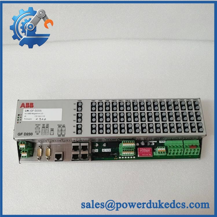
ABB GFD233A103 3BHE022294R0103
Module 4: Dynamic Emergency Swap & Configuration Guide
1. Pre-Swap Prep — Isolate the DC Drive Power Stage
Place the drive in the approved maintenance state and isolate all relevant incoming AC sources. Wait for the DC-link energy to discharge, then verify absence of hazardous voltage with a properly rated meter. Record GFD233A103 / 3BHE022294R0103, drive frame/size, board revision, CT ratio, voltage-input arrangement, resistor-link settings, connector locations, and fault history. Photograph the original board before disconnecting it.
2. Removal — Disconnect the Internal Interfaces Without Disturbing the Power Stage
GFD233A103 is an internal drive interface PCB, not a DIN-rail device. After confirming the power section is safe, disconnect the board’s current-measurement, voltage-measurement, temperature, and controller-interface connections as applicable. The documented controller connection is XC12, while X22 is used for the DCS880 temperature sensor. Four current-measurement channel pairs are identified for the mains-side CT inp
Release the board retention hardware and withdraw the PCB carefully. Keep CT wiring grouped by channel and preserve every jumper or zero-ohm link position. Do not pull on small signal conductors or fiber/control interfaces while extracting the board.
3. Installation & Configuration — Reproduce the Original Measurement Topology
Verify GFD233A103 and 3BHE022294R0103 on the replacement before installation. Fit the board into the same drive position and restore XC12, X22, CT inputs, voltage inputs, and all other connectors exactly as documented.
The voltage-input arrangement is particularly important. The documented interface uses 20–100 VAC through X15, 100–525 VAC through XU2/XV2/XW2/XC2/XD2, 526–1000 VAC through XU1/XV1/XW1/XC1/XD1, and an isolated 100–1200 VAC arrangement through X15 using the specified transducer/transformer arrangem Do not change the zero-ohm resistors or measurement path merely to make the wiring fit.
For current measurement, preserve the original 1:2500 or 1:4000 CT ratio configuration. The burden scaling is handled by the firmware according to the type-code setting described in the technical documentat
4. Power-On Self-Test (POST) — Validate Firing, Feedback, and Temperature
After final wiring inspection, restore power using the drive’s controlled commissioning procedure. Check the drive diagnostics for armature-interface, current-feedback, voltage-feedback, and temperature faults.
Next, verify the measured AC/DC values against calibrated test equipment. Confirm all four CT channels respond correctly, the selected voltage-input path is scaled correctly, and the temperature input is recognized. Before applying a production load, perform a controlled firing/enable test according to the DCS880 service procedure. A successful startup without an interface fault is only the first checkpoint; current feedback and armature-voltage measurement must also agree with the test reference.
Module 5: Quality Assurance & Testing SOP
Each ABB / 3BHE022294R0103 should undergo controlled board inspection and compatible-drive functional testing before shipment.
- OEM anti-counterfeit visual inspection: Verify ABB identification, marking, 3BHE022294R0103 part number, PCB construction, connector geometry, component placement, and revision information.
- Exact part-number verification: Match / 3BHE022294R0103 against the physical board and purchasing record.
- Mechanical inspection: Check PCB edges, mounting points, connector pins, terminal hardware, contamination, corrosion, cracked solder joints, and evidence of unauthorized modification.
- Interface-topology verification: Record the drive size, controller interface, voltage-input path, CT ratio, resistor-link configuration, and temperature interface before electrical testing.
- Power-on self-test (POST): Energize the board within an approved compatible drive/test fixture and verify startup diagnostics.
- Current-measurement test: Inject controlled signals into all four CT measurement channels and verify correct amplitude, channel identity, and scaling.
- CT-ratio verification: Confirm the configured 1:2500 or 1:4000 ratio matches the test fixture and drive configurat
- Voltage-measurement test: Exercise the applicable input path within its documented voltage range and compare measured values against a calibrated source.
- Armature-voltage feedback test: Verify correct DC and AC measurement behavior through the applicable interface.
- Temperature-input test: Simulate the compatible drive temperature-sensor characteristic through X22 and verify correct diagnostic respo
- Thyristor firing test: Where the laboratory fixture permits, verify six- or twelve-pulse bridge firing commands and synchronization behavior without connecting an uncontrolled production load.
- Snubber/protection inspection: Verify the related protection circuitry and interface connections against the approved drive schematic.
- I/O full-range simulation: Exercise applicable analog feedback, temperature, protection, and controller-interface signals throughout the approved test range.
- Fault simulation: Introduce controlled current, voltage, and temperature deviations and verify the drive’s expected alarm or protective response.
- Controller-interface test: Confirm proper communication between the armature interface and the designated SDCS-CON-H01 or SDCS-OPL-H01 interf
- Extended stability test: Run representative measurement and firing activity while monitoring for drift, intermittent faults, unexpected resets, and thermal abnormalities.
- Final QC record: Document board identification, revision, drive compatibility, CT ratio, voltage-input configuration, measured values, diagnostic results, test duration, photographs, technician sign-off, and packaging condition.
Module 6: Maintenance & Reliability FAQ
1. Is ABB a direct drop-in replacement, or does it require a firmware flash?
is a hardware interface board rather than a standalone PLC processor. The available technical description assigns it the armature-circuit interface function, including thyristor firing and measurement circu A firmware flash should therefore not be assumed simply because the board has been replaced. The important checks are the exact 3BHE022294R0103 part number, drive size, CT ratio, voltage-input topology, and associated controller interface.
2. Is it safe to hot-swap while the drive is running?
No. This board interfaces directly with the drive power-conversion and measurement circuits. The associated armature and DC-link circuits can contain hazardous stored energy even after incoming power has been removed. Fully isolate the drive, verify the DC link is safe, and follow the applicable DCS880 service procedure before removing the PCB.
3. Will replacing cause my current program or drive configuration to be lost?
The board is primarily an armature interface and measurement assembly, not the main application-memory controller. Replacing it should not by itself erase the drive application. Still, record and back up the drive parameters, motor data, CT ratio, measurement configuration, firing settings, temperature configuration, and fault history before shutdown. Pay particular attention to the board’s resistor-link and measurement-path configuration.
4. What should I verify before commissioning the replacement?
Confirm , 3BHE022294R0103, the hardware configuration, CT ratio, voltage-input range, resistor-link positions, temperature connection, and controller interface. The documented board supports 1:2500 and 1:4000 CT ratios and several voltage-measurement arrangements extending to 1200 VAC with the specified isolated hardw After installation, perform calibrated current/voltage injection and a controlled armature test before returning the drive to production.
5. What are the warranty terms if the unit fails after installation?
Warranty coverage should be stated on the quotation or sales order for the specific serialized board. Retain the incoming inspection report, nameplate photographs, board revision, CT configuration, voltage-input configuration, pre-replacement fault history, post-installation measurements, and commissioning results. For an armature interface board, this record helps distinguish an internal board fault from CT wiring, voltage-sensing configuration, thyristor-bridge, temperature-sensor, or controller-interface probems.











 Start Chat


