

Description
Module 2: The 10-Second Buyer’s Brief
- Brand: ABB
- Full Model Number: GJR2391511R42
- Associated Product Code: 81EU01E-E
- Associated Part Number: GJR2391500R1210
- System/Series Family: ABB Industrial Automation / Digital I/O
- Core Function: Digital input module for receiving discrete field signals and transferring their status to the control system
- Top 3 Hardcore Specs: Digital input function | 81EU01E-E identification | GJR2391500R1210 / GJR2391511R42 cross-reference
- Stock Status: New surplus / condition to be confirmed per available unit
Available technical references associate GJR2391511R42 with 81EU01E-E and GJR2391500R1210, and describe the assembly as an ABB digital input module. Because the accessible documentation is inconsistent on detailed electrical ratings, channel count, and signal voltage, those values should be verified from the module nameplate or the applicable ABB documentation before a replacement is approved.
Module 3: Technical Product Introduction
When a legacy ABB control cabinet starts reporting multiple missing discrete signals, replacing the wrong I/O board can extend the outage rather than resolve it. GJR2391511R42, associated with 81EU01E-E and GJR2391500R1210, is identified in available technical references as a digital input module used within industrial automation and control applications. Its job is straightforward: accept discrete field-state information and make that status available to the control system.
The important engineering point is signal compatibility. A digital input module must match the installed I/O architecture, field voltage, channel arrangement, terminal configuration, and controller expectations. Publicly available references do not provide enough reliable evidence to state a definitive channel count, input voltage, isolation specification, or response time for GJR2391511R42. —Do not approve a substitution from the base part number alone; verify the complete nameplate and existing cabinet drawings first.
Module 4: Application Scenarios & Field Realities
- For conveyor and material-handling equipment, the module can be used for discrete status signals such as limit switches, proximity devices, interlocks, and equipment-running feedback. The practical concern is signal integrity: a field contact that remains electrically noisy can appear to be an I/O failure when the actual fault is in the wiring or sensor.
- During control-cabinet troubleshooting, multiple lost digital indications should prompt an examination of the common power supply, terminal wiring, and I/O reference points before replacing the module. One failed field circuit does not automatically indicate a failed input board.
- In machine-control applications, discrete inputs commonly represent permissives and sequence conditions. A replacement module therefore needs to reproduce the same electrical input behavior; a visually identical board with a different input specification is not an acceptable substitute.
- For legacy ABB equipment restoration, the GJR2391511R42 identification is particularly useful when the original module is obsolete or difficult to source. Match the complete ordering code, board marking, connector arrangement, and revision. Available references also connect the part to ABB’s 81EU01E-E designation.
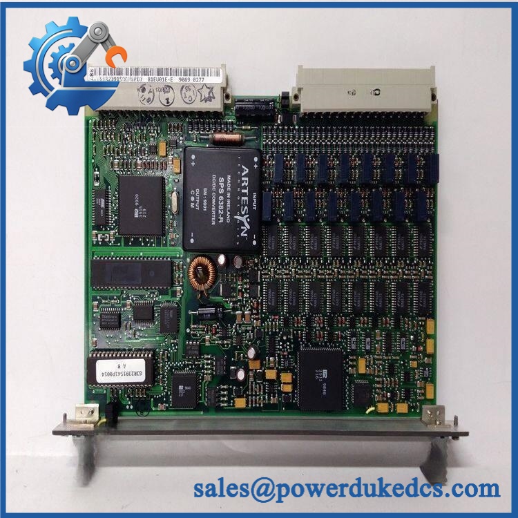
ABB GJR2391511R42
Module 5: Migration, Compatibility & Installation Traps
Replacement Matrix
| Replacement Type | Assessment |
|---|---|
| Drop-in Replacement | Potentially yes, when replacing the same / 81EU01E-E configuration |
| Software Compatible | Normally hardware-dependent; verify controller I/O configuration before commissioning |
| Hardware Modification Required | Not expected for an exact replacement; required if connector, terminal, or electrical specifications differ |
Field Traps — Watch Out
Do not assume the cross-reference is universal. Available references group 81EU01E-E, GJR2391500R1210, and together, but this does not by itself establish interchangeability across every cabinet revision. Verify the original module’s complete identification before purchasing.
Field-voltage mismatch is a serious risk. Before energizing the replacement, compare the existing field circuit voltage and input specification with the actual module documentation. Applying an incompatible voltage can damage the input circuitry or produce unreliable status indications.
Terminal mapping matters. Photograph the original wiring before removal and compare each terminal against the cabinet schematic. Never transfer wires solely by physical position if the replacement revision has a different terminal assignment.
Module 6: Quality Assurance SOP
Before shipment, each available should be processed through a documented inspection sequence:
- OEM identification inspection — Verify ABB markings, designation, associated ordering information, labels, and board revision.
- OEM anti-counterfeit visual inspection — Examine PCB workmanship, component markings, labels, connectors, solder joints, and signs of unauthorized rework.
- Physical condition inspection — Check the enclosure, PCB, terminal/connector interfaces, mounting points, and contact surfaces for cracks, corrosion, contamination, or impact damage.
- Part-number verification — Cross-check the physical module against the customer’s requested specification and any supplied equipment documentation.
- Power-on test — Apply the manufacturer’s specified test conditions where the correct test fixture is available; monitor module behavior and cabinet diagnostics.
- Digital input simulation — Apply controlled input signals corresponding to the verified module specification and confirm that each accessible input changes state correctly.
- Communication/status verification — Confirm that the host control system recognizes the I/O assembly and that simulated input states are correctly reported.
- Fault-condition check — Inspect diagnostic indications for unexpected input faults, supply abnormalities, or communication errors.
- Final visual inspection — Recheck connectors, labels, fasteners, and PCB condition after testing.
- Test record and packaging — Record the serial/identification information, inspection results, test date, and final packing condition before dispatch.
QA note: A digital input module should not be described as having a CPU-style POST unless its specific hardware documentation confirms such a function. For , input-state verification and host-system recognition are more meaningful acceptance tests than an invented RUN/ERR LED procedure.











 Start Chat


