

Description
Module 2: The 10-Second Buyer’s Brief
- Brand: ABB
- Full Model Number: 83SR06B-E
- ABB Part Number: GJR2395400R1210
- System/Series Family: 83SR06B-E
- Core Function: Industrial control and power-management module
- Top 3 Hardcore Specs: 220 V operating voltage | 50 kHz listed output frequency | GJR2395400R1210 ordering reference
- Physical Reference: Approx. 400 × 350 × 250 mm reported by secondary sources
- Stock Status: New surplus, factory-sealed, or tested refurbished subject to current inventory confirmation
Public product records consistently associate GJR2395400R1210 with the ABB 83SR06B-E designation. Secondary listings report a 220 V operating-voltage figure and identify the unit as an industrial control module; however, the available public data is inconsistent on its exact functional classification, so the installed nameplate and ABB documentation should be treated as the final authority.
Module 3: Technical Product Introduction
A replacement request for GJR2395400R1210 needs more than a model-number match. The part is publicly listed as ABB 83SR06B-E GJR2395400R1210, but third-party descriptions disagree on whether it should be categorized as a logic module, power module, or other control-system component. That distinction matters when restoring an installed cabinet: connector arrangement, electrical ratings, firmware, and the surrounding system architecture must all correspond. For procurement, the safest identification is therefore the complete 83SR06B-E / GJR2395400R1210 combination rather than the ABB prefix alone.
Published secondary data lists 220 V as the operating-voltage figure and 50 kHz as an output-frequency specification. Another listing reports approximately 400 × 350 × 250 mm and 30 kg, while a separate source lists approximately 3.2 kg, demonstrating that these physical specifications should not be treated as interchangeable without checking the actual unit and enclosure configuration.
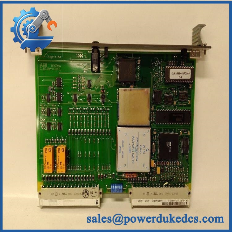
ABB GJR2395400R1210 83SR06B-E
Module 4: Application Scenarios & Field Realities
- For an installed ABB control cabinet with a failed 83SR06B-E, the first field task is identification, not installation. Record the complete part number, revision, terminal arrangement, and existing diagnostic condition before removing the original unit.
- Where the module is associated with motor or industrial control equipment, verify the cabinet’s incoming supply and control-voltage requirements against the actual nameplate. A published 220 V figure should not be interpreted as proof that every installation uses the same supply configuration.
- During a planned maintenance shutdown, this part can be held as a direct spare only after the installed hardware has been cross-checked. Photographing terminal positions and identification labels before replacement is worthwhile; it prevents a surprisingly common wiring-identification error during recommissioning.
- For long-obsolete equipment, retaining the original hardware architecture may be preferable to redesigning an otherwise functional control panel. The engineering calculation should include panel modifications, commissioning time, software changes, and process downtime—not only the purchase cost of the replacement.
Module 5: Migration, Compatibility & Installation Traps
Replacement Matrix
| Replacement Type | Assessment | Engineering Requirement |
|---|---|---|
| Drop-in Replacement | Potentially applicable when replacing the same 83SR06B-E / configuration | Verify complete part number, revision, electrical rating, and connector arrangement |
| Software Compatible | Application-dependent | Confirm the installed controller architecture and any associated configuration or firmware requirements |
| Hardware Modification Required | Not expected for an exact same-part replacement | Do not substitute a different ABB module solely because its electrical rating appears similar |
Field Traps — Watch Out
1. Functional-description conflict: Public supplier records describe this exact part in materially different ways, including a high-frequency power supply module, logic input module, and electronic overload relay. Those descriptions cannot all be assumed correct. The physical ABB nameplate, technical drawing, and the original equipment documentation should control the final application decision.
2. Electrical-rating assumption: Several listings state 220 V, but that figure alone is insufficient to determine whether the unit can be substituted into a particular cabinet. Verify supply voltage, frequency, current requirements, terminal allocation, protective devices, and the complete circuit diagram before energization.
3. Dimensional and weight discrepancy: Reported weights range from approximately 3.2 kg to 30 kg, with one source also giving 400 × 350 × 250 mm dimensions. This is a strong indication that some online records may describe different packaging, assemblies, or incorrectly classified equipment. Confirm actual physical dimensions from the unit in hand before designing shipping packaging or cabinet clearance.
Module 6: Quality Assurance SOP
Before shipment, each unit should be processed through a documented inspection sequence. Identification accuracy is especially important for this part because publicly available descriptions are inconsistent.
- Step 1 — Part-number verification: Record ABB 83SR06B-E, , revision information, serial number, and all visible secondary markings.
- Step 2 — OEM anti-counterfeit visual inspection: Examine ABB labels, printing quality, PCB or assembly markings, connector construction, fasteners, terminal markings, and manufacturing identifiers. Photograph the nameplate before testing.
- Step 3 — Physical condition inspection: Check for corrosion, cracked housings, damaged terminals, bent pins, contamination, impact marks, loose hardware, and evidence of previous unauthorized repair.
- Step 4 — Electrical inspection: Verify the unit’s applicable input and output ratings against the documented equipment specification. Do not apply power solely on the basis of a third-party listing.
- Step 5 — Power-on self-test (POST): Where the correct ABB test environment is available, energize the unit under controlled conditions and record all available status indicators, including ERR/RUN or equivalent diagnostic states.
- Step 6 — Communication and functional verification: Where applicable to the installed architecture, perform the required control-system handshake and verify expected signal or status response. Record the test configuration and observed result.
- Step 7 — Identification cross-check: Compare the tested unit against the customer’s requested reference again before packing. A visually similar ABB module is not an acceptable substitute without engineering approval.
- Step 8 — Final photographic record: Photograph the complete unit, nameplate, connectors, visible revision markings, and packaging condition. Retain the records with the shipment file.
QA release criterion: The unit should not be represented as fully tested unless the appropriate electrical and system-level test environment was actually available. If only visual and electrical checks were possible, state that limitation clearly in the inspection report.











 Start Chat


