

Description
- Brand: ABB
- Full Model Number: GVC714A101 / 3BHE024415R0101
- Associated Power Device: 5SHX1060H0003 / 3BHB020538R0001
- Associated Device Reference: 5SXE07-0164; 5SGX1060H00003E.S.
- Lifecycle Status: Legacy medium-voltage power-electronics hardware
- Core Function in System: Gate-drive control for high-power IGCT switching devices
- Top 3 Hardcore Specs: GVC714A101 gate-drive assembly; 3BHE024415R0101 ABB article number; matched to 68 mm 5SHX 1060H0003 RC-IGCT
- System Association: ABB ACS 5000 / related medium-voltage converter architectures
- Form Factor: Converter gate-drive/control assembly
- Condition & Lead Time: New OEM or tested legacy inventory; emergency dispatch subject to confirmed stock
ABB-associated product records identify 3BHE024415R0101 as GVC714A101, while ABB catalog information for 3BHB020538R0001 identifies it as the 5SHX 1060H0003, 68 mm RC-IGCT used as the associated power device in an ACS 5000 Water Cooled drive.
Module 3: Technical Intro & Downtime Impact
A failed GVC714A101 can stop a converter power cell from receiving the correct gate-drive commands even when the upstream control system remains operational. That makes this a high-value troubleshooting point in a medium-voltage drive: a gate-drive fault can present as an inverter fault, switching failure, or power-cell trip. The ABB GVC714A101 / 3BHE024415R0101 is documented in market and application references as the gate-drive/control assembly associated with ABB high-power IGCT converter hardware.
The surrounding hardware must be identified as a complete electrical set. ABB catalog data identifies 3BHB020538R0001 as 5SHX 1060H0003, 68 mm RC-IGCT, with a listed net weight of 1.93 kg, and identifies its application as the ACS 5000 Water Cooled drive. The gate-drive board and power semiconductor therefore should not be treated as interchangeable generic parts. (For emergency replacement work, compare the exact board revision, fiber interface, gate connection, and matched power-device identification before energization.)
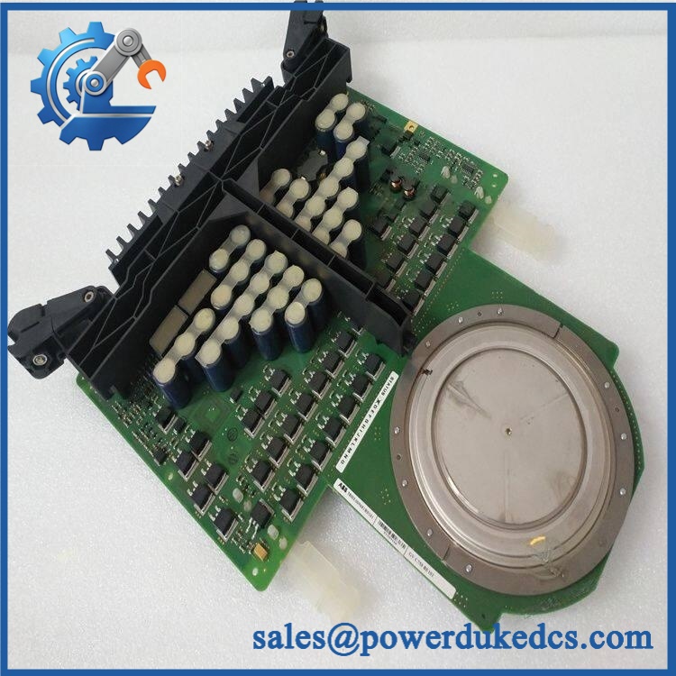
ABB GVC714A101 3BHE024415R0101
Module 4: Dynamic Emergency Swap & Configuration Guide
1. Pre-Swap Prep — Secure the Power Cell
Place the ACS/medium-voltage converter in its approved maintenance state and complete the plant LOTO procedure. Confirm the DC-link and all stored-energy sources have been discharged according to the drive service manual. Record the GVC714A101 / 3BHE024415R0101 identification, board revision, fiber connections, gate-circuit connections, and the associated power-device marking.
For systems using the associated 5SHX1060H0003 / 3BHB020538R0001 device, document the exact phase or power-cell position before removing the gate-drive assembly.
2. Removal — Disconnect Fiber and Gate Connections in Sequence
After verifying a safe electrical state, photograph the complete gate-drive interface before disconnection. Disconnect the control/fiber interfaces first as specified by the equipment procedure, then isolate the gate-drive power and gate connections. Release the mechanical retainers and remove the without bending fiber leads or stressing the gate connection.
Inspect the board, optical connectors, gate interface, and surrounding power-cell hardware for carbon tracking, heat discoloration, cracked insulation, or evidence of a previous semiconductor failure.
3. Installation & Configuration — Match the Power Device Pairing
Install the replacement / 3BHE024415R0101 in exactly the same position and reconnect each interface to its original point. The supplied board should be checked against the associated power-device identification before commissioning.
Do not invent jumper or DIP-switch values. Where configuration links, fiber assignments, or gate-drive settings are specified by the converter drawing, reproduce them exactly. The associated 5SHX 1060H0003 RC-IGCT is a specific 68 mm device, so verify that the gate-drive assembly is being paired with the correct semiconductor family.
4. Power-On Self-Test (POST) — Verify Gate Command and Feedback
Restore auxiliary control power before applying converter power. Check the drive controller for gate-drive, optical-link, power-cell, and protection diagnostics. Confirm that the communicates correctly with the converter control system and that the expected feedback signals return from the gate-drive circuit.
Before enabling the full power stage, perform the manufacturer’s approved low-energy gate-pulse or converter commissioning test. Validate the gate command path, fault feedback, and interlocks. Only after these checks pass should the power cell be exposed to normal operating voltage.
Module 5: Quality Assurance & Testing SOP
The ABB / 3BHE024415R0101 should be tested as a gate-drive assembly matched to the converter’s power semiconductor.
- Identity verification: Record , 3BHE024415R0101, hardware revision, serial number, and all associated power-device references.
- OEM anti-counterfeit visual inspection: Check ABB labels, PCB markings, connector geometry, component placement, optical interfaces, and manufacturing identifiers.
- Mechanical inspection: Examine the PCB, mounting points, gate interface, optical connectors, insulating components, and retaining hardware.
- Power-on self-test (POST): Install the board in an approved test environment and verify normal startup and absence of controller-side gate-drive diagnostics.
- Optical-interface test: Verify the transmit/receive path used between the converter controller and the gate-drive assembly.
- Gate-command simulation: Apply controlled gate-drive commands using the approved test fixture and verify correct response.
- Gate waveform verification: Measure the gate-drive waveform with appropriately rated isolated instrumentation; verify timing, polarity, and waveform shape against the applicable ABB test specification.
- Protection-feedback test: Verify that the gate-drive protection and fault-feedback path reports simulated abnormal conditions correctly.
- Power-device compatibility check: Confirm that the gate-drive assembly is matched to the installed 5SHX1060H0003 / 3BHB020538R0001 or the exact power-device type specified by the converter drawing.
- Thermal observation: Operate the assembly under representative conditions and monitor for abnormal heat generation.
- Extended runtime test: Monitor optical communication, gate-drive stability, and fault feedback for intermittent failures.
- Final QC record: Retain identification photographs, firmware/hardware records where applicable, waveform captures, protection-test results, test date, technician sign-off, and final pass/fail status.
The available ABB catalog evidence confirms that 3BHB020538R0001 is the 5SHX 1060H0003 68 mm RC-IGCT and that it is applied in the ACS 5000 Water Cooled platform.
Module 6: Maintenance & Reliability FAQ
1. Is ABB a direct drop-in replacement, or does it require a firmware flash?
Do not assume a blind swap. / 3BHE024415R0101 is a gate-drive/control assembly operating as part of a larger converter control system. Verify the hardware revision, optical interface, gate connection, installed power-device type, and the converter’s applicable software configuration before commissioning. A firmware update should only be performed when the equipment documentation explicitly requires it.
2. Is it safe to hot-swap while the converter is running?
No. Treat the gate-drive assembly as non-hot-swappable. It interfaces directly with high-power semiconductor switching hardware, and live removal can interrupt gate control or protection functions. Complete the manufacturer’s isolation and DC-link discharge procedure before accessing the board.
3. Will replacing cause my current drive program to be lost?
The is a gate-drive/control assembly rather than the primary drive application-storage controller. Replacing the board should not be treated as replacing the main control CPU. Nevertheless, back up the converter configuration and record hardware/software revisions before replacement so the gate-drive interface can be validated against the existing application.
4. What should I verify after installing ?
Verify board identity, hardware revision, optical communication, gate connections, protection feedback, and compatibility with the installed power semiconductor. The associated 5SHX 1060H0003 / 3BHB020538R0001 is a specific 68 mm RC-IGCT, so the gate-drive pairing must agree with the converter documentation. Then perform the approved low-energy gate-pulse test before enabling the power stage.
5. What are the warranty terms if the unit fails post-installation?
Warranty should follow the commercial terms for the exact supplied unit and condition. Retain the serial number, pre-shipment test results, board-revision photographs, gate-waveform records, optical-link test results, installation date, and commissioning report. Those records help distinguish a failed from a damaged optical link, incorrect gate connection, power-semiconductor fault, or converter-control problem.











 Start Chat


