

Description
- Brand: ABB Bailey
- Full Model Number: IMASI23
- System/Series Family: Harmony Rack I/O / INFI 90 OPEN
- One-Sentence Core Function: 16-channel universal analog input module for thermocouple, RTD, millivolt, voltage, and current process signals
- Top 3 Hardcore Specs: 16 analog input channels; 24-bit A/D conversion; individually configurable channels
- Input Types: Thermocouple, millivolt, RTD, high-level voltage, 4–20 mA
- Signal Isolation: Isolated analog inputs
- Conversion: One A/D converter per channel
- Mounting: Single-slot MMU installation
- Bus Interface: I/O expander bus
- Termination: P3 field-signal interface through termination unit
- Addressing: S1 DIP switch
- Compatibility: Direct replacement for IMASI03 / IMASI13 with configuration changes
- Related Platform: Symphony Plus SPASI23 fit-and-function replacement
- Stock Status: New Surplus / Fully Tested Refurbished subject to availability
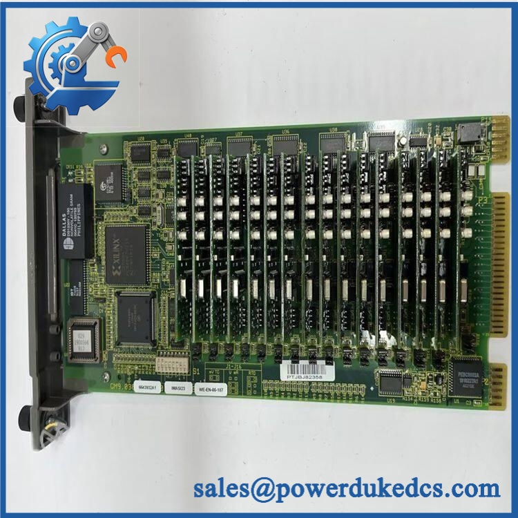
ABB IMASI23
Module 3: Commercial-Technical Deep Dive
When an INFI 90 analog-input channel starts drifting, fails open-input detection, or reports implausible process values, replacing the entire controller is the wrong level of intervention. The ABB Bailey IMASI23 is a 16-channel Harmony Rack analog input module designed to interface isolated thermocouple, millivolt, RTD, and high-level analog signals with the controller. Each channel has its own analog-to-digital converter and can be configured independently, allowing mixed signal types on one module rather than forcing an entire card to one measurement technology. ABB documentation identifies 24-bit A/D conversion and compatibility with existing INFI 90 OPEN systems.
The architecture is also useful during troubleshooting. The IMASI23 contains an onboard microcontroller and memory, performs input processing locally, and communicates with the controller through the I/O expander bus. The field devices do not terminate directly on the PCB; P3 interfaces to the termination cable, while P1 handles supply voltages and P2 connects to the expander bus. A single S1 DIP switch handles module addressing and onboard test selection, while jumpers determine analog-input configuration. ABB states that IMASI23 can directly replace IMASI03 or IMASI13 with minor modifications, including changes to function-code 216 specification S11 and a review of power-supply sizing because power consumption differs.
Module 4: Compatibility & Installation Traps
Migration/Compatibility
- System: ABB Bailey Harmony Rack I/O / INFI 90 OPEN
- Module Type: Universal analog input module
- Channels: 16
- A/D Resolution: 24-bit
- Input Configuration: Independently configurable by channel
- Signal Classes: Thermocouple, millivolt, RTD, high-level voltage, and 4–20 mA
- Installation: One MMU slot
- Bus: I/O expander bus
- Termination: Field signals enter through the termination unit and P3 connector
- Replacement Relationship: ABB documents IMASI23 as a direct replacement for IMASI03 and IMASI13, with minor configuration modifications.
- Modern Family Relationship: ABB documentation identifies SPASI23 as a fit-and-function replacement for IMASI23 within Symphony Plus.
- Logic Rewrite: Not normally required for the module itself, but Function Code 216 specification S11 must be reviewed when migrating from IMASI03/IMASI13.
- Power Review: Recalculate system power/current requirements when replacing older modules.
⚠️ Field Traps (Watch Out)
1. Do not copy the old resolution configuration blindly.
ABB specifically calls out a change to Function Code 216, specification S11 when replaces IMASI03 or IMASI13. The newer module supports different resolution choices, so the existing configuration must be reviewed before returning the loop to service.
2. Verify the S1 address before installation.
The module uses a DIP switch for its module address or onboard testing. A replacement board can pass a bench power test and still remain invisible to the intended controller if its address does not match the original configuration.
3. Do not move field wires directly onto the module PCB.
P3 connects to the termination cable, while actual field wiring is located at the termination unit. Preserve the original termination architecture during replacement.
4. Power-budget changes are easy to miss.
ABB explicitly recommends checking power-supply sizing and system current requirements when migrating from earlier ASI modules. A replacement that fits mechanically can still expose a marginal rack power supply.
Module 5: Quality Assurance SOP
Each ABB unit should pass a documented receiving and functional-test sequence before shipment:
- OEM anti-counterfeit visual inspection: Verify ABB Bailey identification, marking, board artwork, connector placement, front-panel labeling, and manufacturing markings.
- Part-number verification: Confirm the physical unit is , not IMASI03, IMASI13, IMASM03, or another similarly named analog module.
- PCB condition inspection: Check for corrosion, contamination, cracked components, damaged edge connectors, loose hardware, thermal discoloration, and previous repair evidence.
- Connector inspection: Verify P1, P2, and P3 connector integrity, including contacts and mechanical retention.
- S1 configuration inspection: Record DIP-switch position before testing and compare it with the intended test configuration.
- Jumper inspection: Verify analog-input configuration jumpers against the approved laboratory configuration.
- Power-on self-test (POST): Install the module in an approved Harmony Rack/MMU test system and verify normal initialization.
- Bus handshake verification: Confirm successful communication between the and the controller through the I/O expander bus.
- Channel-by-channel analog testing: Apply controlled simulated inputs to all 16 channels using the supported input classes and verify expected digital values.
- Mixed-input test: Where the fixture permits, operate multiple channels with different input types to verify independent channel configuration.
- Thermocouple simulation: Test selected thermocouple channels using a calibrated simulator.
- RTD simulation: Verify representative RTD configurations using a precision resistance source.
- 4–20 mA verification: Apply calibrated current signals and confirm correct acquisition.
- Voltage/millivolt verification: Check representative low-level and high-level voltage ranges.
- Open-input and fault detection: Verify the module reports applicable open-input or diagnostic states under controlled conditions.
- Resolution/configuration check: Confirm the module’s programmed resolution against the intended Function Code configuration, particularly after /IMASI13 migration.
- Final QC record: Record catalog number, revision/trace information where available, S1 setting, jumper configuration, all tested channels, measured deviations, and technician sign-off.
- ESD-safe packaging: Package the module using ESD-protective material with mechanical support around the card-edge connectors and front-panel latches.
The module’s design supports meaningful bench validation because input processing is performed locally by the onboard microcontroller before data is passed to the controller. A proper outgoing report should therefore include actual channel measurements, not simply a power-up statement.
Module 6: CRO-Driven Buyer FAQ
What is the ABB used for?
The ABB Bailey is a 16-channel universal analog input module for Harmony Rack I/O within the INFI 90 OPEN architecture. It accepts isolated thermocouple, millivolt, RTD, voltage, and current signals and converts those measurements into digital data for the controller.
Can replace or ?
Yes. ABB explicitly documents as a direct replacement for , but the migration is not simply a physical card swap. Function Code 216 specification S11 must be reviewed for the different resolution choices, and rack power/current calculations may need to be checked.
Can the be installed with the system powered?
ABB documentation for the related architecture indicates these modules can be removed or installed without powering down the system. However, the exact maintenance procedure should follow the installed INFI 90/Harmony rack design and site rules; do not infer live replacement suitability solely from the module family.
What should I verify before ordering an ?
Confirm the model, existing MMU and termination-unit arrangement, S1 module address, input-channel configuration, resolution settings, and whether the current system is migrating from or . Also verify rack power capacity because ABB specifically calls for a power-budget review during this replacement.
What warranty and technical support should I expect?
Warranty duration should be stated for the exact unit condition and test status on the quotation. Technical support should cover model identification, / compatibility review, channel configuration, S1 address verification, installation guidance, and documented analog-input test results. INFI 90 application engineering or control-logic modification should be treated separately unless explicitly included.











 Start Chat


