

Description
- Brand: ABB
- Full Model Number: KSD211B / 3BHE022455R1101
- ABB Catalog Designation: KS D211 B101
- Product Type: Input Coupling Unit ICU
- Lifecycle Status: Legacy UNITROL 6000 excitation-system spare
- Core Function in System: Input signal coupling and supervision interface within UNITROL 6000 static excitation systems
- Top 3 Hardcore Specs: 70 V supervision application | 120 mm length | 165 mm height
- Product Width: 50 mm
- Product Net Weight: 0.5 kg
- Application Platform: UNITROL 6000 static excitation systems
- Country of Origin Listed by ABB: Switzerland
- Condition & Lead Time: New or verified surplus inventory subject to stock confirmation; expedited dispatch for stocked units
ABB’s own excitation spare-parts listing identifies 3BHE022455R1101 as KS D211 B101, with the description “ICU Input Coupling Unit (70V supervision)” under the UNITROL 6000 family. ABB-linked product data lists the unit at 120 mm × 165 mm × 50 mm with a 0.5 kg net weight.
Module 3: Technical Intro & Downtime Impact
A supervision-interface failure inside a static excitation system can be deceptive. The generator may remain mechanically available while the excitation controller reports abnormal supervision, missing feedback, or an invalid input condition. The ABB KSD211B 3BHE022455R1101 is cataloged as the KS D211 B101 Input Coupling Unit, specifically associated with 70 V supervision in ABB’s UNITROL 6000 spare-parts documentation. Its job is to provide the required input coupling/interface path rather than act as the main excitation controller.
For maintenance planning, the verified physical data are compact: 120 mm length, 165 mm height, 50 mm width, and 0.5 kg net weight. ABB’s spare-parts record places the part in the UNITROL 6000 static excitation system category. Public sources retrieved here do not provide enough authoritative ABB information to state a universal input-current rating, exact coupling ratio, insulation class, operating-temperature range, or MTBF for every KSD211B installation. Those values should come from the applicable UNITROL electrical drawing. That caution matters because an incorrect coupling configuration can produce a valid-looking signal with the wrong electrical interpretation.
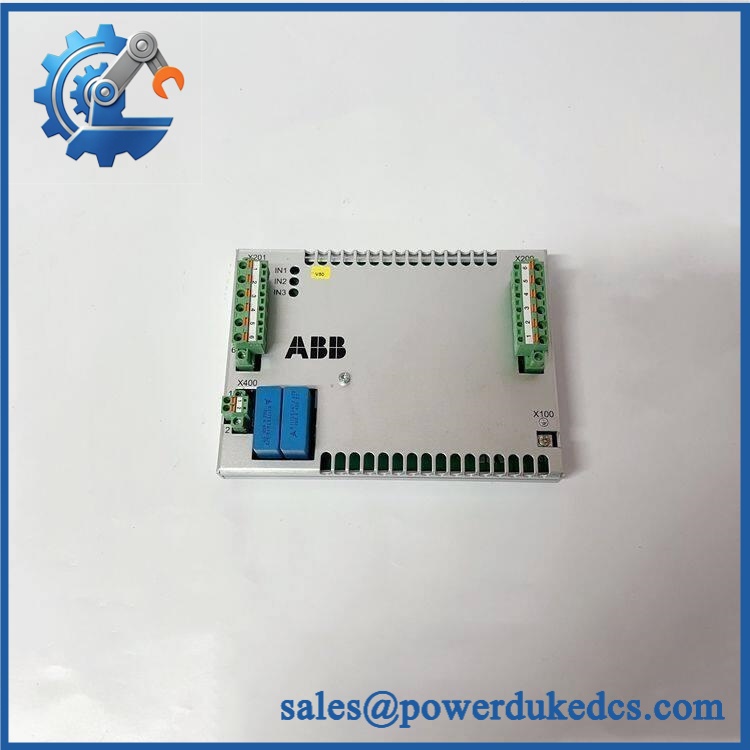
ABB KSD211B 3BHE022455R1101
Module 4: Dynamic Emergency Swap & Configuration Guide
1. Pre-Swap Prep — Verify the 70 V Supervision Circuit
Apply the plant’s approved UNITROL 6000 shutdown and LOTO procedure. Verify that the relevant excitation cabinet circuits are electrically safe before opening the enclosure.
Record the complete KSD211B / 3BHE022455R1101 identification, serial number, cabinet location, connected terminals, signal designations, cable routing, and any configuration references on the electrical drawing. Photograph the original unit before disconnecting it.
The 70 V supervision designation should be treated as a hard compatibility check, not a descriptive label. ABB specifically identifies this product as the KS D211 B101 ICU with 70 V supervision.
2. Removal — Release the Cabinet-Mounted Coupling Unit
Once the circuit is confirmed de-energized, label each conductor and connector before removal. Disconnect the input and output signal wiring by the connector or terminal hardware rather than pulling the cable.
Release the mounting hardware and remove the KSD211B while supporting the 0.5 kg assembly. Inspect the wiring terminals for oxidation, discoloration, loose crimping, or evidence of overvoltage. Those findings can be important when determining whether the coupling unit was the root cause or the victim of another fault.
3. Installation & Configuration — Match the Original Supervision Path
Mount the replacement KSD211B / 3BHE022455R1101 in the same cabinet position and restore all wiring according to the UNITROL 6000 electrical drawing.
Check the signal path carefully before energization. The ABB catalog description identifies this part as a 70 V supervision ICU, while secondary listings associate the same order number with the /KSD211B101 designation. Do not substitute another coupling-unit variant simply because its enclosure dimensions appear similar.
There is no reliable evidence here supporting a universal firmware-download procedure for the . Configuration should be determined by the connected UNITROL hardware and the approved electrical schematic.
4. Power-On Self-Test (POST) — Validate Signal Transfer and Supervision
Restore control power according to the approved startup procedure. Check the UNITROL diagnostic system for input-coupling, supervision, or signal-path alarms.
Then verify the supervised signal against a calibrated reference. Where permitted by the commissioning procedure, inject a known test signal into the coupling circuit and confirm that the expected value reaches the control system without abnormal scaling, instability, or fault indication.
A continuity check alone is not enough. The ‘s function is signal coupling and supervision; the acceptance test should prove the complete signal path.
Module 5: Quality Assurance & Testing SOP
Each available ABB / 3BHE022455R1101 should pass a documented electrical and mechanical QA sequence before shipment:
- OEM anti-counterfeit visual inspection — verify ABB markings, designation, KS D211 B101 reference, 3BHE022455R1101 identification, serial label, enclosure, terminals, and manufacturing markings.
- Part-number reconciliation — compare the physical unit with the customer’s UNITROL 6000 BOM and the exact electrical drawing.
- Catalog-description verification — confirm the required application is the ICU Input Coupling Unit for 70 V supervision. ABB lists 3BHE022455R1101 under UNITROL 6000.
- Dimensional inspection — verify approximately 120 × 165 × 50 mm against the documented product data.
- Weight verification — confirm approximately 0.5 kg net weight where practical.
- Connector and terminal inspection — check every electrical interface for bent contacts, corrosion, cracked insulation, loose terminals, and heat damage.
- Insulation and grounding checks — perform the applicable safety tests using test levels appropriate to the actual UNITROL circuit.
- Controlled power test — energize the unit only in a compatible laboratory fixture and record supply conditions.
- Power-on self-test (POST) checking for excitation-system diagnostics — verify that the connected UNITROL test controller reports normal interface status.
- 70 V supervision simulation — apply a controlled reference signal appropriate to the documented circuit and verify the expected response.
- Signal-transfer test — measure the input and output side under multiple representative operating points and compare against the approved reference values.
- Isolation verification — confirm the required electrical separation between the relevant coupling sides using the test procedure specified by the equipment documentation.
- Fault simulation — where the test fixture permits, simulate a controlled open-circuit or out-of-range input and verify the expected UNITROL diagnostic response.
- Extended operation test — run the interface under representative signal activity and monitor stability, thermal behavior, and intermittent faults.
- Final QA record — retain label photographs, serial information, dimensional checks, test readings, supervision-signal results, insulation records, and final packaging photographs.
ABB’s documented identification is particularly useful here: 3BHE022455R1101 = KS D211 B101 = ICU Input Coupling Unit with 70 V supervision. That exact chain should appear in the supplier’s test record.
Module 6: Maintenance & Reliability FAQ
Is the ABB 3BHE022455R1101 a direct drop-in replacement, or does it require a firmware flash?
It is a hardware Input Coupling Unit rather than a programmable CPU. ABB identifies the part as for 70 V supervision in UNITROL 6000 systems. Firmware flashing is therefore not normally the primary replacement task. Compatibility should instead be established from the exact UNITROL electrical drawing, supervision circuit, terminals, and hardware revision.
Is it safe to hot-swap the while the excitation system is running?
Do not assume it is safe. The is installed inside an excitation-control system and may be connected to energized supervision circuits. Use the approved UNITROL shutdown and LOTO procedure before disconnecting the unit unless the exact system documentation explicitly authorizes energized maintenance.
Will replacing the cause my current excitation program to be lost?
The is an input-coupling interface, not the primary excitation controller or application database. Replacing it should not by itself erase the controller’s application program. Maintain backups of the UNITROL configuration and record all relevant supervision parameters before planned maintenance.
What should I verify before ordering an emergency spare?
Verify , 3BHE022455R1101, and the ABB catalog designation . Most importantly, confirm that the application requires the 70 V supervision ICU identified by ABB. Also check the cabinet drawing, terminal arrangement, PCB or hardware revision, and the installed UNITROL 6000 system generation.
What are the warranty terms if the coupling unit fails after installation?
Warranty depends on the supplying party and the purchase agreement. Confirm the warranty period, DOA coverage, test scope, and return procedure before shipment. Retain the pre-shipment identification record, electrical test results, supervision-signal measurements, and commissioning report. Those records provide a useful baseline when separating a defective from an upstream excitation-circuit or wiring fault.











 Start Chat


