

Description
- Brand: ABB
- Full Model Number: MFE190-04UP-03A0-2+N7550
- Product Family: MicroFlex e190
- Core Function in System: AC servo motion control for precision motor applications
- Rated Output Current: 3.0 A
- Maximum Output Current: 4.5 A at the standard overload rating; up to 7.5 A under the 300% overload mode for 3 seconds
- Input Voltage: 200–240 VAC ±10%
- Input Frequency: 50/60 Hz
- Output Frequency: 0–500 Hz
- Encoder Interface: Universal encoder interface
- Programming: P = programmable
- Construction: Frame size 04
- Memory / Option Reference: +N7550 configuration; verify the installed nameplate and ordering code before replacement
- Condition & Lead Time: Stock condition subject to inspection; emergency dispatch available subject to order confirmation
ABB’s published MicroFlex e190 data identifies MFE190-04UP-03A0-2 as a 3 A, 200–240 VAC servo drive with universal encoder capability and programmable operation. ABB’s rating table gives 4.5 A maximum output at the lower overload setting and 7.5 A for the 300% / 3-second overload mode.
Module 3: Technical Intro & Downtime Impact
When a servo axis stops during production, the problem is rarely confined to the drive itself. A failed power stage, encoder interface fault, or internal drive error can leave the machine unable to home, position, or complete its cycle. ABB MFE190-04UP-03A0-2+N7550 belongs to the MicroFlex e190 servo-drive family and is specified for a 3.0 A rated output with a 200–240 VAC ±10% input supply. Its universal encoder architecture is intended for servo feedback applications where accurate position and velocity control are required.
From an MTTR standpoint, exact type-code matching matters more than simply finding another 3 A drive. The published 03A0 rating corresponds to 3.0 A continuous RMS current, while ABB lists 6.0 A at the 200% overload setting and 7.5 A at the 300% overload setting for three seconds, subject to the applicable operating conditions. ABB also specifies a 0–500 Hz output-frequency range for the MicroFlex e190 family. The replacement should therefore be checked against the motor nameplate, encoder arrangement, machine tuning data, safety wiring, and exact type designation before power is restored.
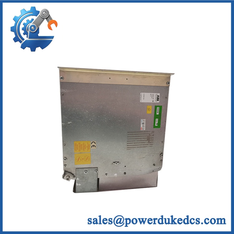
ABB MFE190-04UP-03A0-2+N7550
Module 4: Dynamic Emergency Swap & Configuration Guide
1. Pre-Swap Prep — Save the Axis Before Opening the Cabinet
Lock out the AC supply and verify the DC bus is discharged with an approved meter. ABB’s documentation explicitly warns of hazardous voltages at the AC input and motor-output terminals. Record the drive nameplate, firmware information, motor data, encoder configuration, Mint program or machine application data where applicable, parameter values, and STO wiring. Photograph the existing terminal connections before disassembly.
2. Removal — Disconnect the Power and Control Wiring in Order
The MicroFlex e190 is a compact wall-mounted drive with removable connection points for power, motor, control, and feedback wiring. After confirming zero hazardous voltage, disconnect the AC input, motor U/V/W connections, DC or braking connections where fitted, control power, safety inputs, and encoder wiring. Label each connector before removal. Do not pull the encoder cable by its conductors; preserving shield termination and connector orientation is critical to a clean restart.
3. Installation & Configuration — Match the Complete Type Code
Mount the replacement in the same cabinet position and restore each connection against the original wiring record and ABB drawing. Confirm the complete designation MFE190-04UP-03A0-2+N7550, not just the MFE190 prefix. The type code identifies the 04 frame, UP configuration, 03A0 current class, and 2 input-voltage rating. ABB identifies the P designation as programmable.
For programmable applications, verify the application’s memory/configuration arrangement before startup. ABB documentation explains that the MicroFlex e190 memory unit stores the drive firmware and saved parameters, and on programmable variants it also carries the Mint program. The memory unit must be fitted, and ABB specifies that power must be removed before inserting or removing it.
4. Power-On Self-Test (POST) — Prove the Axis Before Production Release
Apply power under controlled conditions and inspect the drive status indications and diagnostic information. Confirm that the drive initializes without an active fault, the safety circuit is healthy, encoder feedback is detected, and the commanded motor direction agrees with the machine documentation. With the motor disconnected from the mechanical process where practical, perform a low-speed jog or controlled commissioning test. Watch actual current, feedback stability, fault codes, and following error before releasing the axis to production.
Module 5: Quality Assurance & Testing SOP
Each ABB MFE190-04UP-03A0-2+N7550 should be evaluated as a complete servo drive, with its exact type designation and configuration preserved throughout inspection.
- OEM anti-counterfeit visual inspection: Check ABB labels, type-code format, serial number, compliance markings, enclosure construction, connectors, terminal geometry, and PCB workmanship.
- Exact part-number verification: Confirm
MFE190-04UP-03A0-2+N7550against the quotation, inspection record, and physical nameplate. - Mechanical inspection: Examine the housing, cooling path, mounting points, connector locks, terminal blocks, and signs of corrosion, impact, overheating, or unauthorized repair.
- Power-input verification: Confirm the unit is configured for the specified 200–240 VAC ±10% supply range before energization.
- Power-on self-test (POST): Apply controlled power and verify startup behavior, fault status, internal diagnostics, and normal operating indications.
- DC-bus verification: Measure charging and discharge behavior against the applicable service documentation before proceeding to motor testing.
- Encoder simulation / feedback test: Connect an approved motor-feedback source or compatible motor and verify stable encoder identification and actual-speed feedback.
- Motor output test: Run a controlled motor test and verify phase output, direction, current response, acceleration, deceleration, and fault handling.
- I/O full-range simulation: Exercise applicable digital inputs, enable signals, STO inputs, relay/status outputs, analog interfaces, and configured control signals.
- Overload verification: Where the laboratory test fixture permits, verify current response against the documented 3 A continuous class and applicable overload configuration without exceeding the approved test limits.
- Application/configuration verification: For programmable units, confirm the retained application, parameters, firmware association, and memory configuration before release.
- Final QC record: Record serial number, type code, firmware data, measured values, fault history, inspection photographs, test results, technician sign-off, and packaging condition.
Module 6: Maintenance & Reliability FAQ
1. Is ABB +N7550 a direct drop-in replacement, or does it require a firmware flash?
A physical replacement is not automatically a commissioning-ready replacement. The 03A0 current class and 2 voltage code must match the existing drive, while the UP and programmable configuration also need to agree with the machine application. ABB states that the MicroFlex e190 memory unit stores firmware and saved parameters, and programmable versions can also store the Mint program. A firmware update should therefore be based on an actual compatibility requirement, not performed simply because a replacement drive has been installed.
2. Is it safe to hot-swap this drive while the system is running?
No. The MicroFlex e190 carries hazardous AC input and motor-output voltages, and ABB’s wiring documentation explicitly warns of hazardous voltage at the relevant terminals. Completely isolate the drive, verify DC-bus discharge, and follow the plant’s electrical safety procedure before removal.
3. Will replacing this drive cause my current program to be lost?
It can, depending on where the application’s data is stored and whether the replacement retains the required memory configuration. ABB states that the e190 memory unit stores firmware and saved parameters and, on programmable variants, the Mint program. Before removal, make an external backup of parameters and the application and document the existing memory-unit identification. Never remove or insert the memory unit with power applied.
4. What should I verify before commissioning the replacement?
At minimum, verify the complete type code, input voltage, 3 A current class, motor compatibility, encoder type, safety wiring, application data, and tuning parameters. ABB’s rating data identifies 3.0 A continuous current, with overload capability dependent on the selected operating mode. A replacement that powers up correctly can still fail commissioning if its motor, encoder, or application configuration does not match the original.
5. What are the warranty terms if the unit fails after installation?
The applicable warranty should be stated in the sales order for the specific serialized unit. Keep the incoming inspection photographs, nameplate record, installation date, commissioning results, fault history, and post-installation test data. For a servo drive, those records are especially useful when separating a drive fault from an encoder, motor, cable, STO, or machine-load problem.











 Start Chat


