

Description
- Model: P7LA
- ABB Part Number: HNEF105323R0002
- Brand: ABB
- Series: ETL600
- Part Type: Power Subrack / Power Amplifier Rack
- Core Function: Houses the power-supply and RF-related plug-in assemblies used within the ABB ETL600 communication system.
- Key Specs: Supports B5LA or B5LC power-supply units, accommodates the E5TX transmitter filter and P3LE RF hybrid, with the P1LA power amplifier mounted at the rear.
- Primary Application: ABB ETL600 power-line carrier and industrial communication equipment.
Product Introduction
When an ETL600 communication installation develops a power or RF hardware fault, replacing individual plug-in boards may not be enough if the underlying rack assembly has damaged connections or degraded interfaces.
The ABB P7LA HNEF105323R0002 is identified as a power subrack associated with ABB’s ETL600 equipment. ABB’s ETL600 documentation describes the P7LA as the rack that houses the power supply, transmitter filter, and RF hybrid, while the P1LA power amplifier is mounted at the rear.
The rack is therefore a mechanical and electrical platform for several functional assemblies rather than a conventional PLC I/O module. The exact installed configuration should be checked before replacement, particularly the power-supply version and RF arrangement.
Core Technical Specifications
| Parameter | Value |
|---|---|
| Manufacturer | ABB |
| Model | P7LA |
| ABB Part Number | HNEF105323R0002 |
| Product Family | |
| Product Type | Power Subrack |
| System Function | Power / RF Equipment Rack |
| Compatible Power Supply | B5LA or B5LC |
| B5LA Supply | 48 VDC input |
| B5LC Supply | 115/230 VAC input |
| Transmitter Filter | E5TX |
| RF Hybrid | P3LE |
| Power Amplifier | P1LA |
| RF Interface | Coaxial connections |
| Installation | equipment rack |
| Application | Industrial Power-Line Communication |
| Typical System | |
| Part Classification | ABB Communication Equipment Spare |
| Replacement Strategy | Exact Part Number and Configuration Match |
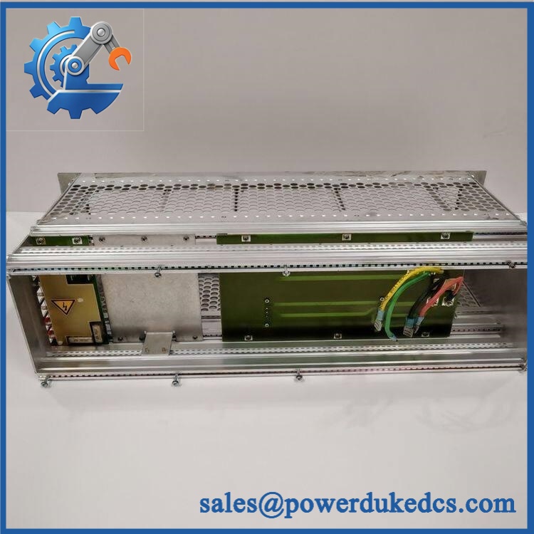
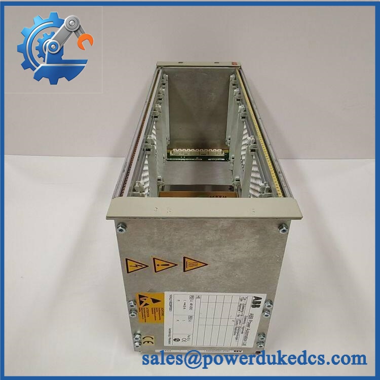
ABB P7LA HNEF105323R0002
ABB’s manual specifically identifies P7LA as the power subrack and lists B5LA/B5LC, E5TX, and P3LE as assemblies housed within it; the P1LA power amplifier is mounted at the rear.
Application Scenarios & Pain Points
Within an electrical utility communication system, P7LA forms part of the equipment architecture used for power-line carrier communication. The rack provides the physical platform for power and RF assemblies required by the communication equipment.
For substations with legacy equipment, a damaged rack interface can affect several installed assemblies at once. Checking the backplane, connectors, power connections, and RF connections is necessary before replacing individual plug-in units.
During scheduled communication-system maintenance, technicians can inspect the rack together with the B5LA/B5LC supply, E5TX filter, P3LE hybrid, and P1LA amplifier. This approach helps identify whether a communication failure originates in the rack or in a plug-in assembly.
Where 48 VDC battery-backed power is used, the documentation specifies the B5LA configuration for external 48 VDC supply. Stable DC input and correct polarity are important during maintenance.
For installations exposed to elevated cabinet temperatures above 50°C, inspect rack contacts, power connectors, RF interfaces, and ventilation. Thermal cycling can contribute to contact degradation and intermittent communication faults.
Common Error Codes & Diagnostic Symptoms
Symptom/Code: equipment fails to power up
→ Diagnosis: Check the external supply, circuit protection, /B5LC installation, rack power connections, and internal interfaces.
→ Action: Verify the supply path and replace the if the rack itself is confirmed defective.
Symptom/Code: Intermittent RF communication
→ Diagnosis: Inspect the RF connections, P3LE hybrid, E5TX filter, P1LA amplifier connections, coaxial cabling, and rack contacts.
→ Action: Isolate the RF path and replace the defective rack assembly or affected plug-in component.
Symptom/Code: Plug-in module not operating after replacement
→ Diagnosis: Check module seating, backplane contacts, rack connectors, supply rails, and the exact configuration.
→ Action: Reseat and electrically verify the assembly; replace the if the interface is damaged.
Cross-Reference & Lifecycle Migration
Product Identification
The requested identification is:
- ABB Model:
- Part Number: HNEF105323R0002
- System:
- Product Type: Power Subrack
- Primary Function: Houses power and RF assemblies
ABB’s documentation confirms that is a power subrack and describes its internal equipment arrangement.
Configuration Compatibility
Before ordering a replacement, verify:
- part number
- Installed or power supply
- E5TX filter configuration
- P3LE RF hybrid
- amplifier arrangement
- Rear RF connections
- External power architecture
- Cabinet mounting arrangement
A rack should not be selected solely because it has the same physical dimensions. The installed configuration must be matched.
Lifecycle Strategy
The is a mature ABB communication platform, so should be treated as a legacy-system spare. For utilities and industrial sites that still depend on equipment, keeping a tested rack assembly can be useful when original sourcing lead times are uncertain.
A practical buffer-stock record should include the part number, installed plug-in units, power-supply type, RF configuration, hardware condition, test history, and storage date.
Firmware flashing is generally not the defining replacement activity for a passive rack/subrack assembly. Physical configuration, power compatibility, and RF connectivity are more important.
Field Engineer’s Tech Notes
Tech Note 1 — Do not confuse the rack with the power supply.
is the power subrack, while and are the power-supply units installed within the rack. ABB documentation explicitly separates these components.
Tech Note 2 — Verify the RF connections before energizing.
The rack carries RF-related assemblies and rear connections. Inspect coaxial interfaces and confirm that unused connectors are properly protected before operation (RF equipment should not be energized with an incorrectly terminated configuration).
Strict QA & Testing SOP
- Part Number Verification
Confirm / HNEF105323R0002 against the purchase order. - Nameplate Inspection
Photograph all ABB identification markings and hardware labels. - Mechanical Inspection
Check the rack frame, mounting points, guide rails, covers, and mechanical interfaces. - Backplane Inspection
Inspect internal contacts and connectors for corrosion, contamination, or mechanical damage. - Power Interface Inspection
Verify the installed / arrangement and inspect power terminals. - RF Interface Inspection
Examine coaxial connectors and RF interfaces for physical damage. - Continuity Test
Perform appropriate continuity checks on accessible power and interface paths. - Controlled Assembly Test
Install the rack into a suitable test configuration. - Power Distribution Test
Confirm correct power distribution to the installed assemblies. - RF Path Verification
Where suitable test equipment is available, verify the relevant RF signal path. - Extended Operation Test
Monitor power and communication stability under controlled conditions. - Thermal Inspection
Check for abnormal heating around power and RF interfaces. - Final Documentation
Record rack identification, installed modules, measured values, test conditions, and test date. - Protective Packaging
Protect the rack with anti-static material and sufficient impact protection during shipment.
Test videos can be provided when available, together with actual product photographs and inspection records.
Buyer’s FAQ
Q1. What exactly is the ABB ?
is an power subrack. It provides the rack structure and interfaces for assemblies including /, , and , while the power amplifier is mounted at the rear.
Q2. Is itself a power supply?
No. is the subrack. The documentation identifies and as the actual power-supply units installed in the .
Q3. What is the difference between and ?
According to ABB’s documentation, is used with a 48 VDC external supply, while is used with 115/230 VAC. The applicable configuration must match the site’s supply system.
Q4. Can I replace while the is energized?
Do not assume hot-swapping capability. Isolate the equipment and follow the applicable maintenance procedure before removing the rack or any installed assembly.
Q5. What should I check before buying a replacement ?
Provide the complete HNEF105323R0002 identification and, if possible, photographs of the installed rack. Also record the / type, , , , and RF connection arrangement.
Q6. What should I request from the supplier?
Request actual nameplate photographs, confirmation of , product condition, inspection/test records, warranty terms, and return conditions. For a critical installation, ask for photographs of the rack interfaces before shipment.











 Start Chat


