

Description
- Brand: ABB
- Full Model Number: PMA324BE / HIEE401111R0006
- Lifecycle Status: Legacy excitation/control hardware
- Core Function in System: Analog regulation and control within generator excitation equipment
- Top 3 Hardcore Specs: PMA324BE designation; HIEE401111R0006 part number; analog excitation-regulation board architecture
- System Association: ABB generator excitation systems / UNITROL-related equipment
- Form Factor: PCB control board
- Configuration: Application-specific hardware; verify revision and terminal/interface arrangement
- Condition & Lead Time: New old stock or tested replacement; emergency availability subject to confirmed physical inventory
A secondary ABB spare-parts listing explicitly identifies PMA324BE HIEE401111R0006 as an industrial process-control board, while another source lists the same PMA324BE model against HIEE400923R0001. Because of this identifier conflict, the HIEE401111R0006 marking should be treated as the controlling procurement reference for the unit supplied.
Module 3: Technical Intro & Downtime Impact
A failed excitation-regulation board can affect generator voltage control, excitation response, reactive-power behavior, and ultimately the generator’s ability to remain in service. The maintenance impact is often larger than the board itself: a regulator fault can trigger excitation alarms, limit operation, or force a generator shutdown while technicians determine whether the problem originates in the regulator, sensing circuit, power stage, or wiring. The specific PMA324BE HIEE401111R0006 identifier is associated by available secondary documentation with ABB excitation-system regulation hardware.
This is a control-board replacement, so the key MTTR variables are hardware revision, signal-interface mapping, calibration/configuration, and compatibility with the installed excitation system. Exact voltage, current, terminal assignment, and dynamic-regulation characteristics should not be copied from unrelated PMA324BE listings because HIEE400923R0001 is also sold under the designation with a different functional description. (For an aging excitation cabinet, inspect the sensing inputs, power supply, connector contacts, and adjacent regulation boards before declaring the defective.)
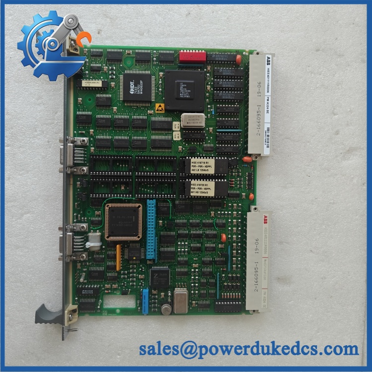
ABB PMA324BE HIEE401111R0006
Module 4: Dynamic Emergency Swap & Configuration Guide
1. Pre-Swap Prep — Preserve Generator Excitation Parameters
Place the generator/excitation system into its approved maintenance state and complete the site’s LOTO and electrical-isolation procedure. Record the complete HIEE401111R0006 identification, hardware revision, serial number, terminal connections, jumper positions, calibration values, and software/configuration references. Back up the excitation controller settings and event records before board removal.
Use ESD protection, insulated tools, the excitation-system schematic, and calibrated electrical test equipment.
2. Removal — Disconnect Sensing and Regulation Interfaces Carefully
After confirming the excitation system is de-energized, photograph every connector and terminal before disconnection. Label voltage/current sensing inputs, regulator outputs, feedback wiring, and communication connections individually. Release the board retainers and withdraw the carefully from its mounting position or backplane.
Do not pull against terminal wiring. Inspect the surrounding board and connector area for heat discoloration, corrosion, loose terminals, or evidence of an upstream power-supply problem.
3. Installation & Configuration — Match the Exact Build
Install the replacement in the identical position and reconnect all interfaces against the original schematic. Reproduce the original jumper and hardware configuration only where it is explicitly documented for the installed excitation system.
Do not substitute configuration information from the frequently listed HIEE400923R0001 variant. That identifier is separately documented as a processor/Modbus-related configuration, which demonstrates why the complete article number matters here.
4. Power-On Self-Test (POST) — Prove Regulation Before Generator Loading
Restore auxiliary power and verify normal controller startup, self-supervision, and excitation-system diagnostics. Confirm that sensing values are plausible and that no regulator or analog-input fault is active.
Next, perform the approved excitation-system functional test at low energy or according to the generator commissioning procedure. Verify voltage-reference tracking, feedback scaling, regulator response, limiters, alarms, and control transitions before allowing the generator to assume normal operating load. Do not rely on a healthy display alone.
Module 5: Quality Assurance & Testing SOP
The ABB should receive a controlled excitation-regulator acceptance test.
- Identity verification: Record , , serial number, hardware revision, board markings, and installed-system reference.
- OEM anti-counterfeit visual inspection: Inspect ABB labels, PCB markings, component arrangement, connectors, terminal construction, fasteners, and manufacturing identifiers.
- Mechanical inspection: Check PCB condition, edge contacts, connector pins, mounting points, terminals, and signs of overheating or corrosion.
- Power-on self-test (POST): Energize the board on an approved excitation-system test fixture and verify normal initialization and self-supervision status.
- Supply verification: Confirm the board receives the correct auxiliary supply specified by the installed excitation-system drawing; do not infer the value from another listing.
- Analog-input simulation: Inject calibrated representative sensing signals and verify correct displayed and processed values.
- Full-range signal testing: Test low, nominal, and upper-range sensing values within the approved system limits.
- Regulation-output test: Exercise the regulator output using an approved controlled load or excitation test setup and confirm the expected response.
- Feedback-loop verification: Confirm correct polarity, scaling, channel assignment, and response of voltage/current feedback circuits.
- Limiter and alarm test: Simulate approved abnormal conditions and confirm correct alarm, limiting, and protective responses.
- Dynamic response test: Verify reference changes, controlled transitions, and stable regulator response using the applicable excitation test procedure.
- Extended runtime test: Operate the board under representative conditions to identify intermittent analog drift, resets, abnormal heating, or unstable regulation.
- Final QC record: Retain identification photographs, configuration backup, calibration data, signal-injection results, alarm-test results, test date, technician sign-off, and final pass/fail disposition.
The association is supported by a current secondary listing describing the as an excitation-system regulating board. At the same time, other sources associate with HIEE400923R0001, so the final QA record should explicitly capture the complete part-number chain.
Module 6: Maintenance & Reliability FAQ
1. Is ABB a direct drop-in replacement, or does it require a firmware flash?
Do not assume a blind replacement. The designation is used in conflicting secondary records, including and HIEE400923R0001. For the supplied unit, verify the complete identification, hardware revision, excitation-system application, connector layout, and configuration before installation. A firmware procedure should only be performed when required by the specific ABB system documentation.
2. Is it safe to hot-swap this board while the generator is running?
No. Treat the board as non-hot-swappable unless the exact excitation-system maintenance documentation explicitly provides a live replacement procedure. It is connected to generator sensing and regulation circuits, so uncontrolled removal can compromise excitation control and protective functions.
3. Will replacing cause my current excitation program to be lost?
The physical board replacement does not automatically mean that the generator’s complete control configuration is erased, but the replacement board should not be assumed to contain the exact site configuration. Back up regulator parameters, calibration values, limiters, I/O assignments, communication settings, and event records before removal.
4. What should I verify after installing ?
Verify the exact article number, hardware revision, auxiliary supply, analog-input scaling, signal polarity, regulator outputs, feedback values, alarms, limiters, and excitation response. Because appears under more than one part-number association in secondary sources, the nameplate and system drawing should be the primary compatibility check.
5. What are the warranty terms if the unit fails post-installation?
Warranty should follow the commercial terms for the exact supplied unit and condition. Retain the serial number, pre-shipment test report, hardware-revision photographs, configuration backup, calibration measurements, installation date, and commissioning results. Those records help distinguish a failed regulator board from a sensing-transformer issue, incorrect calibration, auxiliary-power fault, wiring problem, or another excitation-system fault.











 Start Chat


