

Description
- Brand: ABB
- Full Model Number: PPD103B101
- ABB Part Number: 3BHE020455R0101
- Lifecycle Status: Legacy installed-base excitation-system controller
- Core Function in System: Excitation-system control and signal-processing board
- Top 3 Hardcore Specs: Modbus communication; excitation control application; industrial generator control interface
- System Association: ABB/Alstom excitation and generator-control systems
- Communication: Modbus reported by field inventory records
- Condition & Lead Time: New, tested, or refurbished inventory; emergency dispatch subject to confirmed stock
Available technical records consistently associate PPD103B101 / 3BHE020455R0101 with ABB excitation-control applications. One matching listing identifies Modbus as the communication interface, while other records classify the unit as an excitation-system controller or control board. The exact cabinet architecture should therefore be verified before replacement.
Module 3: Technical Intro & Downtime Impact
A failed excitation controller can turn a localized electronics fault into a generator outage. Loss of excitation control affects generator voltage regulation and can trigger protective actions, inhibit synchronization, or prevent a unit from returning to service. The ABB PPD103B101 3BHE020455R0101 is identified in available records as an excitation-control board used within ABB/Alstom generator excitation systems.
This is a component where exact identification matters more than generic electrical similarity. Field listings associate the PPD103B101 with Modbus communications, while other descriptions identify it as an excitation-system control board. Because public documentation does not provide a sufficiently reliable complete electrical specification for this exact part number, values such as supply voltage, I/O count, memory capacity, and operating temperature should be taken from the installed cabinet documentation or OEM technical drawings rather than guessed. —that distinction can prevent a spare from being installed into a technically similar but incompatible excitation platform.
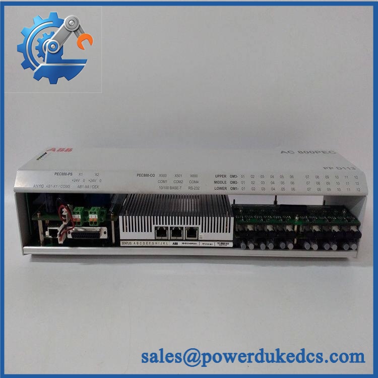
ABB PPD103B101 3BHE020455R0101
Module 4: Dynamic Emergency Swap & Configuration Guide
1. Pre-Swap Prep — capture the excitation system state
Place the generator/excitation system into the plant-approved maintenance condition and complete LOTO as required. Photograph the PPD103B101 nameplate, PCB orientation, connector positions, LEDs, wiring labels, and adjacent controller hardware. Record the installed 3BHE020455R0101 identifier, hardware revision, firmware information if accessible, communication parameters, and existing excitation-system configuration. Use ESD protection and a calibrated multimeter.
2. Removal — preserve the connector and board relationship
After approved isolation, tag every connector before disconnecting it. Record connector orientation and terminal references rather than relying on wire color alone. Release the board from its rack, carrier, or retaining mechanism using the cabinet’s actual mechanical arrangement, then withdraw it straight to avoid stressing the backplane connector. Inspect the connector contacts and board guides for oxidation, contamination, or evidence of thermal damage.
3. Installation & Configuration — restore the original control architecture
Seat the replacement PPD103B101 in the same position and reconnect every interface according to the original wiring drawing. Verify the correct supply polarity and measured voltage before energization. Restore applicable communication parameters, node/address settings, application configuration, and excitation-system parameters from the approved backup. Do not substitute another PPD-series board simply because the mechanical dimensions appear similar.
4. Power-On Self-Test (POST) — validate the excitation path before startup
Energize the control section under the approved commissioning procedure. Check the board’s initialization and diagnostic indicators, then verify controller communication and the expected Modbus data exchange where applicable. Confirm excitation feedback, voltage-reference signals, permissives, alarms, and protection interlocks. Only after the complete control path has been validated should the generator be returned to the approved start-up sequence.
Module 5: Quality Assurance & Testing SOP
The should receive board-level identification and functional checks before entering emergency-spare inventory.
- OEM Anti-Counterfeit Visual Inspection: Verify ABB markings, designation, 3BHE020455R0101 part number, PCB construction, connector layout, labels, and revision markings against known reference hardware.
- Serial and Identity Traceability: Photograph the complete nameplate and record serial number, hardware revision, and visible manufacturing identifiers.
- Mechanical Inspection: Check card guides, mounting points, PCB edges, connectors, terminal interfaces, and retaining hardware.
- Power-Up Verification: Apply the documented system supply under controlled laboratory conditions and monitor startup current and initialization behavior.
- Power-On Self-Test (POST): Record all available RUN, status, warning, and fault LED states.
- Communication Test: Verify controller recognition and test the applicable communication interface; available field records identify Modbus for this exact model.
- I/O and Signal Simulation: Exercise the documented control and feedback channels against the approved test specification.
- Excitation Logic Verification: Confirm representative voltage-reference, feedback, permissive, alarm, and control states where the test bench supports the application.
- Fault-Diagnostic Check: Introduce controlled abnormal states where permitted and verify that expected diagnostic behavior is produced.
- Extended Powered Test: Monitor the board during an extended operating period for intermittent faults, communication dropouts, or abnormal thermal behavior.
- Final QC Record: Release only after part-number verification, test results, serial traceability, photographs, and inspection sign-off are complete.
Because public sources provide incomplete and sometimes conflicting technical data for this legacy component, the shipment test should be built around the customer’s actual excitation-system configuration instead of invented nominal specifications.
Module 6: Maintenance & Reliability FAQ
1. Is the 3BHE020455R0101 a direct drop-in replacement, or does it require a firmware flash?
Do not assume universal drop-in compatibility. Match the exact / 3BHE020455R0101 identification, hardware revision, cabinet slot, communication configuration, and excitation-system software before installation. Public listings describe the part as an excitation controller/control board, but they do not establish a universal firmware requirement.
2. Is it safe to hot-swap this board while the system is running?
No universal hot-swap authorization could be verified for this exact part. Treat replacement as a de-energized intervention unless the applicable ABB/Alstom excitation-system maintenance procedure explicitly permits live replacement for the specific cabinet and hardware configuration.
3. Will replacing this control board cause my current excitation program to be lost?
The safest procedure is to back up the complete excitation application, controller configuration, communication parameters, protection settings, and commissioning records before removal. A replacement board should never be assumed to contain the customer’s live configuration. After installation, compare the restored configuration against the pre-failure record before enabling the generator start sequence.
4. What should I verify after installing the replacement?
Verify supply voltage and polarity first. Then check board diagnostics, controller communication, Modbus communications where applicable, excitation feedback, reference tracking, permissives, alarms, and protection interlocks. Functional verification should follow the plant’s approved excitation commissioning procedure rather than a simple power-up check.
5. What are the warranty terms if the unit fails post-installation?
Warranty should be tied to the supplied serial number and documented condition—factory-sealed, tested, or refurbished. Coverage should address hardware failure under specified operating conditions while excluding incorrect wiring, overvoltage, ESD damage, unauthorized modification, and configuration errors. The exact warranty period and return procedure should be stated on the quotation before purchase.











 Start Chat


