

Description
- Brand: ABB
- Full Model Number: PXAA401
- ABB Part Number: 3BSE017233R1
- Lifecycle Status: Legacy installed-base DCS component
- Core Function in System: Central processing/control unit within an ABB DCS architecture
- Top 3 Hardcore Specs: Central Unit designation; ABB DCS system component; 3BSE017233R1 hardware identification
- Product Category: DCS System / Central Unit
- Approx. Shipping Dimensions: 38 × 23.5 × 11 cm
- Approx. Shipping Weight: 4.76 kg
- Condition & Lead Time: Tested inventory or factory-sealed stock; emergency dispatch subject to confirmed availability
The exact model-to-part-number match is PXAA401 / 3BSE017233R1, and available inventory records classify the unit as an ABB Central Unit within a DCS system. Public records also list an approximate shipping size of 38 × 23.5 × 11 cm and shipping weight of 4.76 kg.
Module 3: Technical Intro & Downtime Impact
When a central DCS processing unit fails, the resulting outage can extend well beyond one instrument loop. Control execution, system coordination, and communications between connected control functions may be interrupted, leaving maintenance personnel with a system-level fault rather than a single-channel problem. The ABB PXAA401 3BSE017233R1 is identified as a Central Unit used within an ABB DCS system, making exact part-number verification critical before an emergency replacement is released.
For this legacy component, publicly available technical records do not provide a sufficiently verified OEM specification set for CPU frequency, memory capacity, supply tolerance, I/O count, or operating temperature. Those values should therefore be taken from the installed cabinet documentation and equipment manual rather than estimated from similar ABB hardware. The most reliable MTTR strategy is exact hardware identification first, followed by configuration and communication verification after replacement. —particularly important when a central-unit fault has already stopped a running DCS section.
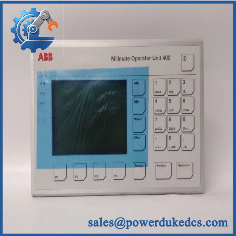
ABB PXAA401 3BSE017233R1
Module 4: Dynamic Emergency Swap & Configuration Guide
1. Pre-Swap Prep — document the Central Unit before isolation
Place the affected DCS section into the plant-approved maintenance condition and execute the required LOTO procedure. Photograph the PXAA401 nameplate, hardware revision, connector arrangement, status indicators, rack location, and adjacent controller hardware. Record the complete 3BSE017233R1 identification, installed firmware or software revision where accessible, communication settings, configuration files, and slot assignment. Use ESD protection and a calibrated multimeter.
2. Removal — preserve the rack and connector arrangement
After approved isolation, label every cable and connector before removal. Record connector locations against the cabinet drawing. Release the Central Unit using the actual rack or mounting hardware fitted in the installation, then withdraw the unit carefully without forcing the backplane interface. Inspect the mating connector, card guides, and surrounding wiring for bent contacts, contamination, corrosion, or heat damage.
3. Installation & Configuration — reproduce the original DCS architecture
Install the replacement PXAA401 in the original position and secure the retaining hardware. Reconnect each interface according to the cabinet wiring and system drawings. Verify the supply voltage and polarity before energizing. Restore the validated DCS configuration, communication parameters, node/address information where applicable, and any required application or database files. The 3BSE017233R1 identification should match the failed unit’s procurement record before the system is commissioned.
4. Power-On Self-Test (POST) — validate controller status and system communications
Apply power according to the approved startup procedure and observe every available status, diagnostic, and fault indicator. Confirm normal controller initialization and verify that the engineering or diagnostic environment recognizes the Central Unit. Check communication with connected control stations and system components, then confirm representative process data, alarms, status indications, and control functions before returning the DCS section to automatic service.
Module 5: Quality Assurance & Testing SOP
The PXAA401 should pass a documented hardware-identification and functional inspection before being released as an emergency spare.
- OEM Anti-Counterfeit Visual Inspection: Verify ABB markings, designation, 3BSE017233R1 part number, PCB construction, connector configuration, labels, fasteners, and revision markings.
- Serial and Identity Traceability: Photograph the complete nameplate and record serial number, hardware revision, and visible manufacturing identifiers.
- Mechanical Inspection: Check card guides, mounting points, connector housings, PCB edges, retaining hardware, and enclosure condition.
- Power Verification: Apply the verified system supply under controlled laboratory conditions and record startup behavior.
- Power-On Self-Test (POST): Check all available RUN, status, warning, and fault LEDs during initialization.
- Controller Recognition Test: Confirm that the test environment identifies the correctly.
- Firmware Verification: Record installed firmware or hardware/software revision information where accessible.
- Communication Test: Verify applicable DCS communication interfaces and controller-to-system communication.
- I/O and Data Simulation: Exercise representative data paths supported by the test setup and verify correct status transmission.
- Alarm Verification: Simulate appropriate diagnostic or process states and confirm expected alarm/status behavior.
- Extended Powered Test: Monitor the Central Unit for intermittent communication faults, unstable initialization, unexpected resets, or abnormal heating.
- Final QC Record: Record model, part number, serial number, test results, photographs, configuration information, and QC approval before shipment.
Available records confirm / 3BSE017233R1 as an ABB Central Unit, while detailed electrical performance data is not sufficiently documented publicly for this specific part. The customer’s original system documentation should therefore establish the final laboratory acceptance limits.
Module 6: Maintenance & Reliability FAQ
1. Is the 3BSE017233R1 a direct drop-in replacement, or does it require a firmware flash?
Do not assume compatibility from the designation alone. Verify the complete / 3BSE017233R1 part number, hardware revision, rack position, firmware compatibility, and DCS configuration before installation. A firmware update should only be performed when the applicable ABB documentation specifically requires it.
2. Is it safe to hot-swap the while the system is running?
Do not assume that this Central Unit supports live insertion or removal. The available evidence does not establish a universal hot-swap procedure for this exact part. Unless the documentation for the specific ABB DCS cabinet explicitly permits energized replacement, use the approved shutdown and isolation procedure.
3. Will replacing this Central Unit cause my current DCS program or configuration to be lost?
The safest practice is to back up the complete DCS configuration before removing the failed unit. Preserve application/database files, controller parameters, communication settings, node information, engineering-station configuration, and relevant diagnostic records. The replacement should never be assumed to contain the site’s active configuration.
4. What should I verify after installing the ?
Verify supply voltage and polarity first. Then confirm controller initialization, diagnostic status, engineering-system recognition, communications, process-data exchange, alarms, status indications, and representative control functions. A normal LED indication alone is not sufficient acceptance evidence.
5. What are the warranty terms if the replacement fails after installation?
Warranty coverage should be tied to the supplied serial number and documented stock condition, such as factory-sealed, tested, or refurbished. Coverage should distinguish genuine hardware failure from incorrect wiring, overvoltage, ESD damage, unauthorized modification, and configuration errors. The exact warranty period and return procedure should be stated on the quotation before purchase.











 Start Chat


