

Description
- Brand: ABB
- Full Model Number: RDCU-12C
- ABB Product ID: 3AUA0000036521
- Lifecycle Status: Legacy ACS800 spare; programmed variants available
- Core Function in System: Drive Control Unit based on the RMIO control board; handles drive I/O, control-panel connection, and PPCS optical communication
- Top 3 Hardcore Specs: 24 VDC ±10% input | 250 mA typical / 1.2 A maximum current consumption | 35 × 7.5 mm DIN-rail mounting
- I/O / Communications: 2 analog current inputs + 1 analog voltage input | 2 analog outputs | 6 digital inputs + DIIL | 3 relay outputs | PPCS optical link
- Operating Temperature: 0 to +60 °C
- Condition & Lead Time: New/surplus stock subject to serial and software verification; expedited shipment available for emergency replacement
ABB’s official product page identifies 3AUA0000036521 as the RDCU-12C Control Board – Programmed. ABB’s hardware manual specifies DIN-rail mounting, 24 VDC input, PPCS fiber communication, and the RMIO-based I/O architecture.
Module 3: Technical Intro & Downtime Impact
At 3 AM, a failed drive control unit can stop an entire converter or motor section even when the power stage itself is healthy. The ABB RDCU-12C provides the control interface between the drive hardware, field I/O, control panel, optional I/O or fieldbus hardware, and the inverter through the ABB PPCS optical link. ABB specifies V57/V68 as the optical interface to the inverter or IGBT supply module, while X39 connects the CDP-312R control panel.
The replacement decision should start with software identity, not only the enclosure. The unit accepts 24 VDC ±10%, draws approximately 250 mA without option modules, and can reach 1.2 A with option modules installed. Six programmable digital inputs, three relay outputs, three analog inputs, and two analog outputs are built into the RMIO-based control architecture. Operating temperature is 0 to +60 °C. The critical MTTR issue is configuration: ABB explicitly instructs technicians to verify the SW TYPE, SW CODE, and DEVICE TYPE before installation. A physically identical spare with the wrong application software is not an acceptable emergency substitute.
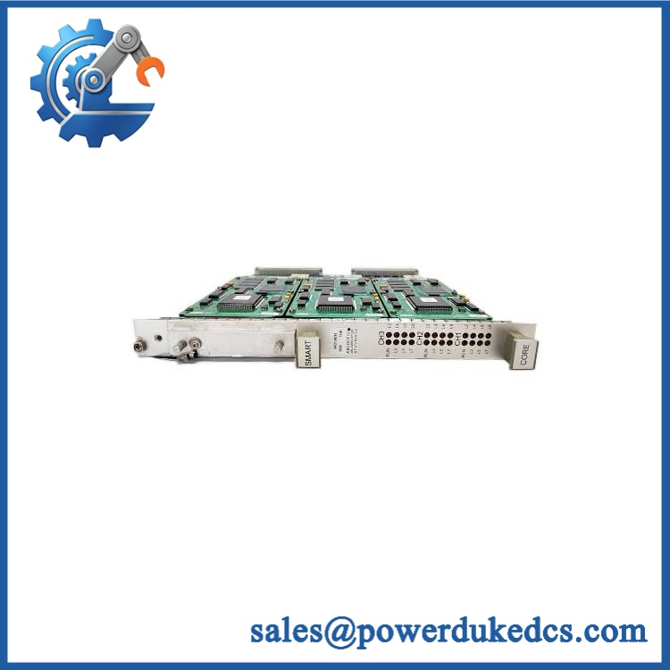
ABB RDCU-12C
Module 4: Dynamic Emergency Swap & Configuration Guide
1. Pre-Swap Prep — Isolate the Drive and Record Software Identity
Apply plant LOTO and verify the drive’s DC bus is discharged before touching the RDCU. ABB specifically warns against working on a powered drive and instructs technicians to verify discharge with a voltage-indicating instrument. Photograph the existing RDCU label and record SW TYPE, SW CODE, and DEVICE TYPE. Also document every terminal and the V57/V68 fiber routing.
2. Removal — Release the DIN-Rail Mounted Unit
Disconnect the detachable screw-terminal plugs and optical/control cables by their connectors. Do not pull on the fiber itself. Remove the two screws securing the RDCU base to the 35 × 7.5 mm DIN rail, then carefully release the upper and lower retaining clips. ABB specifies this exact removal method.
3. Installation & Configuration — Match the Application Package
Install the replacement onto the same DIN rail and secure the two grounding screws. Reconnect X34, X39, V57, V68, and the I/O terminals according to the original wiring record. Confirm the replacement carries the correct application software and device type before applying power; ABB lists common software families including AMXRxxxx for ACS800 System Application Program and ASxRxxxx for ACS800 Standard Application Program.
Do not assume a generic “RDCU-12C” replacement is configured correctly.
4. POST — Confirm Power, Fault State, and Drive Communication
Apply control power and watch the RDCU indicators. ABB specifies a green Power LED indicating +5 V power is OK and a red Fault LED for fault indication. Verify the CDP-312R panel connection at X39, then confirm the PPCS optical link at V57/V68 and perform a controlled drive start test. If the Fault LED remains active, stop troubleshooting at the hardware level until the software package, device type, fiber connections, and application configuration have been checked.
Module 5: Quality Assurance & Testing SOP
Every available ABB RDCU-12C should pass a documented bench and configuration inspection before shipment.
- OEM anti-counterfeit visual inspection — verify ABB markings, RDCU-12C designation, product identification, PCB condition, connectors, terminal blocks, mounting hardware, and manufacturing labels.
- Part-number reconciliation — compare the physical unit against / 3AUA0000036521 and the customer’s approved BOM.
- Software identity verification — record SW TYPE, SW CODE, and DEVICE TYPE from the label or diagnostic environment. ABB specifically requires application-program compatibility to be checked before installation.
- 24 VDC power test — apply controlled 24 VDC ±10% to X34 and verify stable startup current within the expected range for the installed option set.
- Power-on self-test (POST) checking for ERR/Fault and Power LEDs — confirm green Power status and investigate any red Fault indication.
- I/O full-range simulation — exercise the available analog inputs across their specified ranges, including 0/4–20 mA and voltage input ranges; verify the analog output response and programmable digital inputs.
- Relay output verification — test all three programmable relay outputs under controlled load conditions within their rated switching limits.
- PPCS communication test — verify optical communication through V57/V68 using a compatible ABB drive test environment. ABB specifies a 10 MBd optical interface using the PPCS protocol.
- Control panel test — confirm communication with the compatible CDP-312R through X39.
- Final QA record — retain label photographs, measured 24 VDC supply, LED status, I/O test results, software identification, fiber test result, and packing inspection.
A useful field note: option modules materially change current consumption. ABB’s stated maximum is 1.2 A, compared with 250 mA typical without option modules, so a replacement test should reproduce the customer’s actual option configuration where practical.
Module 6: Maintenance & Reliability FAQ
Is the ABB a direct drop-in replacement, or does it require a firmware flash?
It can be a direct physical replacement when the existing hardware configuration matches, but software compatibility must be verified. ABB instructs technicians to check SW TYPE, SW CODE, and DEVICE TYPE before installation. Some replacement units are supplied programmed, while other inventory can require application software loading before use.
Is it safe to hot-swap the while the system is running?
No. The ABB hardware manual instructs technicians not to work on a powered drive and to verify that the intermediate circuit has discharged before beginning work. For a plant emergency replacement, follow the site’s LOTO procedure unless a specific approved system procedure states otherwise.
Will replacing the cause my current drive program to be lost?
The RDCU contains the drive-control hardware and its application software, so replacing it can absolutely create a configuration or software mismatch. Before replacement, back up the drive parameters and application data and record SW TYPE, SW CODE, DEVICE TYPE, I/O settings, and any option-module configuration. ABB’s own manual treats application-program matching as a mandatory pre-installation check.
What happens if the replacement powers up but the drive does not communicate?
Start with the basics: confirm 24 VDC polarity and level at X34, inspect the V57/V68 fiber connections, verify the correct application software and device type, then check the Power and Fault LEDs. The PPCS link is the communication path between the RDCU and the inverter/IGBT supply module, so a damaged or improperly connected fiber can prevent normal drive operation.
What are the warranty terms if the unit fails after installation?
Warranty depends on the supplying party, stock condition, and purchase agreement. The warranty period should be confirmed in writing before shipment, along with DOA coverage, installation-related exclusions, and the return procedure. For control hardware such as the , retain the pre-shipment test record and installation photographs; they provide the clearest evidence when a post-installation fault needs to be separated from wiring, software, or host-drive problems.











 Start Chat


