

Description
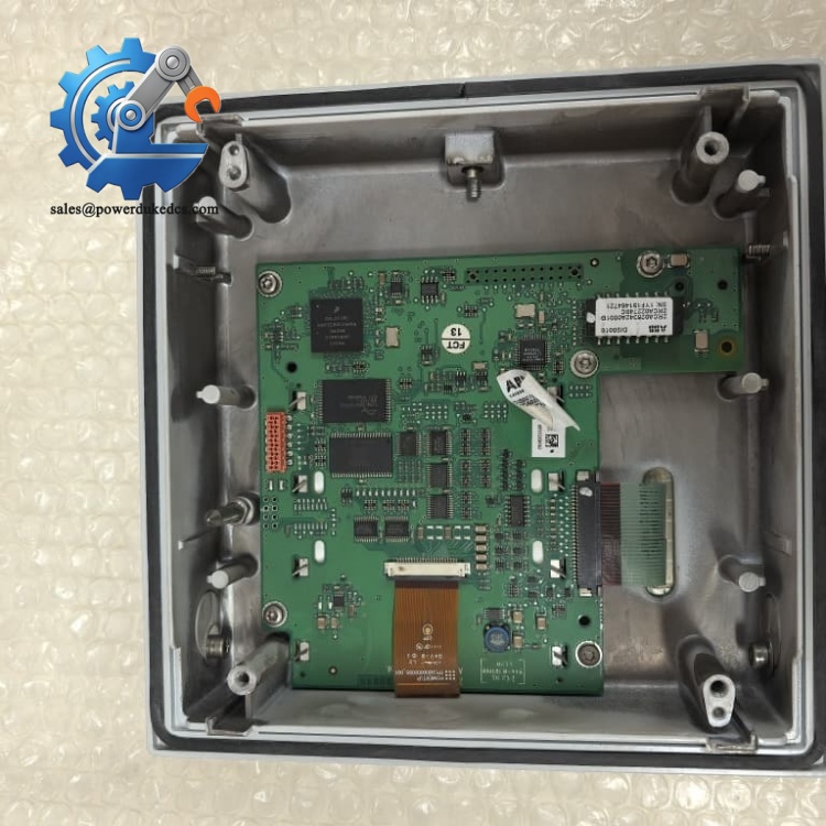
- ABB RED615 RLY-RED615D-G-01 | Integrated Protection, Measurement & Circuit Breaker Control Unit
Product Core Brief
- Model: RED615, RLY-RED615D-G-01
- Brand: ABB
- Series: Relion® 615 Series
- Core Function: Phase-segregated two-end line differential protection for overhead lines and cable feeders
- Type: Numerical Protection & Control IED (Intelligent Electronic Device)
- Key Specs: IEC 61850 compliant, fiber/pilot wire inter-station communication, built-in fault locator
- Condition: New Surplus, factory intact, non-refurbished
⚠️ Long lifecycle medium voltage protection relay; extended factory lead time for new orders
Product Introduction
Key Technical Specifications
| Parameter Item | Technical Specification |
|---|---|
| Full Designation | RED615, RLY-RED615D-G-01 |
| Main Protection Function | Two-end phase-segregated line differential protection (ANSI 87L) |
| Inter-station Communication | Fiber-optic link or galvanic pilot wire connection |
| Supported Protocols | IEC 61850 Ed.1/Ed.2, GOOSE, IEEE 1588v2, Modbus, DNP3, IEC 60870-5-103 |
| Auxiliary Supply | 24–250 V DC / 85–264 V AC |
| Typical Power Consumption | <12 W DC normal operation, max 18 W |
| Operating Temperature | -20 °C to +55 °C |
| Storage Temperature | -40 °C to +85 °C |
| Binary Inputs / Outputs | Configurable, withdrawable plug-in terminal design |
| Additional Functions | Overcurrent backup, earth fault protection, fault locator, disturbance recorder, CB control |
| Mechanical Form | Standard 19-inch withdrawable unit, panel mounting |
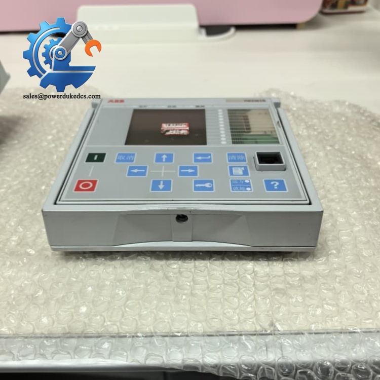
ABB RED615 RLY-RED615D-G-01
Installation & Configuration Guide
Stage 1: Pre-Installation Preparation (15 Minutes)
Stage 2: Old Module Removal (10 Minutes)
Unlock the front panel latch and slide the withdrawable unit outward. Disconnect rear terminal wiring sequentially. Inspect chassis backplane terminals for overheating or corrosion. Keep all wiring labelled to minimise rework.
Stage 3: New Module Installation (18 Minutes)
Critical note: Paired RED615 units must use matching communication parameters and time synchronisation settings.
Stage 4: Power-On & Commissioning (30 Minutes)
Apply auxiliary supply and observe front panel status indicators. Connect PCM600 software to read hardware version and firmware revision. Download saved setting groups. Perform differential communication test between two line-end relays. Run secondary injection test to validate protection pickup characteristics. Maintain continuous monitoring for minimum 60 minutes, confirm no communication loss or self-supervision alarms. Update plant maintenance records with serial number and firmware version.
Standard Quality Inspection SOP
Qualified units are packed in anti-static packaging with QC Pass labels. Inspection photos and test reports are available on request.
Field Replacement Pitfall Guide
Reversed CT wiring creates false differential currents. We encountered a substation case where newly installed relay failed tripping tests purely due to incorrect CT polarity. Always mark and replicate polarity labels during replacement.
Two RED615 devices on the same feeder require compatible firmware versions. Major firmware divergence leads to differential communication handshake failures and protection blocking. Confirm firmware compatibility before ordering spares.
Line differential protection relies on consistent timing. Loss of IEEE 1588 synchronisation increases measurement deviation and risks unwanted protection operation. Verify clock source after commissioning.
For copper pilot wire applications, incorrect shielding grounding introduces induced noise. Follow ABB wiring guide: single-point shielding earth to avoid ground loop currents.
RED615 has multiple standard configurations (A/B/C/D/E). RLY-RED615D-G-01 carries fixed function scope. Direct substitution with other variants will miss required protection functions.
Frequently Asked Questions (FAQ)
It is designed for two-end line differential protection on overhead lines and medium voltage cables. It also works for feeders with in-zone transformers in industrial plants and utility distribution networks.
Mechanical extraction is physically possible, yet feeder protection will be lost during replacement. For safety, only execute replacement during planned outage. Hot swapping is not recommended for primary protection devices.
The core 87L differential function requires two interconnected RED615 IEDs. Standalone operation only enables backup overcurrent and earth fault protection.
Typical symptoms: persistent self-supervision fault alarms, loss of differential communication link, protection functions failing secondary injection tests, disturbance recorder unable to capture fault data.
ABB continues manufacturing Relion 615 series, yet order lead times extend significantly. Sites relying on medium voltage differential protection should maintain planned buffer stock. Long-term migration to REX615 can be evaluated.
All units carry a 12-month industrial warranty. Our team offers remote guidance for PCM600 configuration, differential communication debugging and secondary injection preparation.
Spare Parts Inventory Strategy











 Start Chat


