

Description
- Brand: ABB
- Full Model Number: REF610
- Part Number: 1MRS050692
- Product Series: Relion 610 Series
- Product Type: Feeder Protection Relay
- Lifecycle Status: Not active since 2017; legacy installed-base product
- Core Function in System: Protection, measurement, and supervision of incoming and outgoing distribution feeders
- Top 3 Hardcore Specs: 3-stage phase overcurrent protection; 2-stage non-directional earth-fault protection; 4 accurate current inputs
- Protection: Low-set, high-set, and instantaneous three-phase overcurrent
- Earth Fault: Low-set and high-set non-directional earth-fault protection
- Additional Protection: Phase discontinuity; thermal overload; circuit-breaker failure
- Autoreclose: 1–3 shots
- Current Inputs: Four
- Rated Frequency: User-selectable 50/60 Hz
- Auxiliary Supply: Configuration-dependent; 100–240 VAC / 110–250 VDC or 24–60 VDC variants
- Human-Machine Interface: LCD with local control and indication
- Communication: IEC 61850, IEC 60870-5-103, DNP3, Modbus, Profibus, SPA, LON depending on configuration
- Mounting Architecture: Plug-in relay design
- Condition & Lead Time: Tested inventory or factory-sealed stock; emergency dispatch subject to confirmed availability
ABB identifies REF610 as a feeder protection IED for utility and industrial distribution systems. The relay is primarily intended for incoming and outgoing feeders and uses a removable plug-in design for commissioning and maintenance. ABB also confirms that REF610 has been inactive since 2017.
Important ordering note: ABB’s technical manual shows that a complete REF610 order number contains several configuration fields covering current-input rating, power supply, I/O extension, communication interface, and revision. Therefore, 1MRS050692 alone should be treated as the supplied identification, while the complete relay ordering code on the nameplate should be checked before a direct replacement is approved.
Module 3: Technical Intro & Downtime Impact
A feeder relay failure can remove several protection functions from service at once. A single REF610 may be responsible for phase overcurrent, earth-fault, thermal, phase-discontinuity, breaker-failure, autoreclose, measurement, and trip supervision functions. When the relay is unavailable, the feeder may be blocked from energization—or operators may need to keep the circuit out of service until protection is restored. ABB specifically designed REF610 for incoming and outgoing feeder protection in utility and industrial distribution substations.
The protection set is substantial: three-phase low-set, high-set, and instantaneous overcurrent, low-set and high-set non-directional earth fault, phase discontinuity, cable thermal overload, and circuit-breaker failure are documented functions. also provides four accurate current inputs, disturbance recording, residual-current measurement, phase-unbalance calculation, and configurable trip outputs. Auxiliary-power selection is hardware dependent, with ABB’s ordering key covering 100–240 VAC / 110–250 VDC and 24–60 VDC variants. That makes exact ordering-code verification one of the fastest ways to prevent an installation mismatch during an outage.
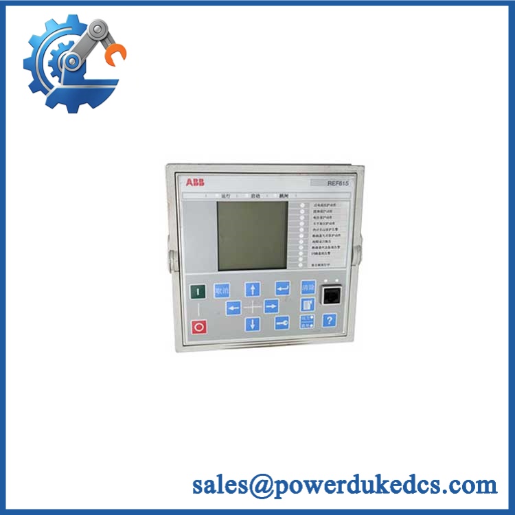
ABB REF610 1MRS050692
Module 4: Dynamic Emergency Swap & Configuration Guide
1. Pre-Swap Prep — capture the complete protection configuration
Place the feeder in the plant-approved maintenance state and follow the site’s electrical isolation procedure. Before removal, photograph the front panel, nameplate, lower marking strip, terminal wiring, LEDs, and communication connections. Record the complete relay ordering code, CT primary/secondary ratios, earth-fault CT arrangement, protection settings, communication protocol, auxiliary supply variant, output assignments, and autoreclose parameters. Do not rely on 1MRS050692 alone; ABB’s ordering structure contains additional hardware-selection fields.
2. Removal — use the withdrawable relay architecture correctly
After approved isolation, release the relay’s mechanical retaining arrangement and withdraw the plug-in unit squarely from its case. Protect the CT circuits throughout the procedure; never leave a current-transformer secondary open when energized. Label communication and auxiliary connections before disconnecting them. Inspect the relay case, mating contacts, terminal area, and CT wiring for overheating, oxidation, or loose connections. ABB specifically describes the 610 series as using a plug-in design that allows fast insertion and withdrawal of the protection relay unit.
3. Installation & Configuration — match CT ratios, power supply, and I/O
Insert the replacement into the original case and secure it. Confirm that the auxiliary supply variant and current-input configuration match the existing relay. Restore protection parameters, output assignments, communication settings, and any autoreclose configuration from the validated backup. Verify whether the installation uses the optional arc-protection hardware, because ABB documents two light-sensor channels as an optional function. The exact configuration matters more than the family name alone.
4. Power-On Self-Test (POST) — prove protection before energizing the feeder
Apply auxiliary power and inspect the front-panel LCD and status indicators. ABB’s self-supervision system continuously monitors relay operation; a permanent internal relay fault causes the green ready indication to flash and an internal-fault code to appear on the LCD. Confirm normal self-supervision, measured phase and residual currents, binary inputs, trip outputs, circuit-breaker status, and communication. Perform an approved secondary-injection test before returning the feeder to service.
Module 5: Quality Assurance & Testing SOP
The should be tested as a numerical protection relay, not merely powered up and inspected.
- OEM Anti-Counterfeit Visual Inspection: Verify ABB and markings, complete ordering code, hardware revision, nameplate, LCD assembly, connector layout, and enclosure construction.
- Serial and Identity Traceability: Record serial number, complete order code, current-input rating, auxiliary-power variant, communication option, and revision.
- Mechanical Inspection: Check the plug-in mechanism, relay case, retaining hardware, terminal interfaces, and mating contacts.
- Auxiliary Supply Verification: Confirm the installed hardware accepts the intended supply before energization; ABB’s ordering key distinguishes the available supply variants.
- Power-On Self-Test (POST): Record LCD startup behavior, ready indication, diagnostic messages, and any internal-relay-fault codes.
- CT Input Verification: Inject calibrated current into all applicable phase-current channels and verify measured values.
- Residual-Current Test: Verify the earth-fault measurement path using the approved secondary-injection method.
- Overcurrent Protection Test: Test low-set, high-set, and instantaneous elements against the approved site settings.
- Earth-Fault Protection Test: Verify low-set and high-set earth-fault pickup and timing.
- Phase-Discontinuity Test: Apply the approved phase-imbalance/discontinuity condition and verify expected relay behavior.
- Thermal Protection Test: Validate the configured thermal model and alarm/trip thresholds where enabled.
- Circuit-Breaker Failure Test: Simulate the applicable breaker-failure condition and verify the programmed logic.
- Trip-Circuit Supervision Test: Confirm supervision status and alarm behavior.
- Binary I/O Full-Range Simulation: Exercise every configured digital input and output used by the installation.
- Arc Protection Test: Where the optional arc hardware is installed, verify both light-sensor channels under the approved test method.
- Communication Test: Verify the installed protocol and remote data exchange using the actual configured interface.
- Disturbance Recorder Test: Create a controlled test event and confirm correct event/disturbance recording.
- Autoreclose Verification: Where enabled, test the programmed 1–3 shot sequence under controlled commissioning conditions.
- Extended Powered Test: Monitor self-supervision, communication stability, LCD operation, and diagnostic status during an extended run.
- Final QC Record: Preserve injection-test results, protection settings, hardware identification, communication configuration, photographs, and final QC approval.
ABB’s technical documentation confirms that provides self-supervision, disturbance recording, measurement, trip-circuit supervision, and configurable protection functions. Those functions should form the basis of the acceptance test rather than a simple power-on check.
Module 6: Maintenance & Reliability FAQ
1. Is the 1MRS050692 a direct drop-in replacement, or does it require a firmware flash?
Do not approve it solely from / 1MRS050692. ABB’s ordering key shows that hardware configurations vary by phase-current input, ground-fault current input, auxiliary supply, I/O extension, communication module, and revision. Compare the complete nameplate ordering code against the failed relay before installation. A firmware change may be required in some configurations, but it should be based on the actual installed hardware and project requirements rather than assumed.
2. Is it safe to hot-swap the while the system is running?
The relay has a withdrawable plug-in design, but that does not mean unrestricted live removal. Follow the switchgear’s approved maintenance procedure. The CT circuit is especially important: never open an energized CT secondary while removing or transferring the relay. For a maintenance outage, de-energized withdrawal is the conservative procedure.
3. Will replacing the cause my current protection program to be lost?
The relay’s protection settings and application configuration should be backed up before replacement. Preserve the complete parameter set, CT ratios, trip logic, communication settings, binary I/O assignments, and autoreclose configuration. The safest workflow is to compare the replacement’s configuration against the pre-failure backup before enabling feeder protection.
4. What should I verify after installing the replacement?
Verify the auxiliary supply and complete hardware ordering code first. Then check CT measurements, residual current, protection pickup and timing, trip outputs, breaker status, trip-circuit supervision, communication, disturbance recording, and all active alarms. ABB’s documentation provides dedicated protection and measurement functions that should be included in the commissioning test.
5. What are the warranty terms if the unit fails post-installation?
Warranty coverage should be tied to the supplied serial number and documented stock condition. Protection-relay coverage should distinguish hardware defects from failures caused by incorrect CT wiring, incorrect auxiliary voltage, unsuitable configuration, installation damage, ESD, or downstream switchgear faults. The exact warranty period and return procedure should be stated on the quotation before purchase.











 Start Chat


