

Description
- Brand: ABB
- Full Model Number: REM610
- Product Family: Relion 610 Series
- Product Type: Motor Protection Relay
- Core Function in System: Protection, measurement, and supervision of asynchronous motors
- Primary Protection: Thermal overload | Phase overcurrent | Earth fault | Phase unbalance | Startup supervision | Running stall
- CT Input: 1 A or 5 A rated current
- Frequency: 50/60 Hz ±5 Hz
- Phase-Current Measuring Range: 0–50 × In(CT)
- Ground-Fault Measuring Range: 0–8 × In(CT)
- Auxiliary Supply: 100/110/120/220/240 VAC or 110/125/220/250 VDC; low-voltage version 24/48/60 VDC
- Dimensions: 177 mm frame width × 177 mm frame height × 149.3 mm case depth
- Relay Weight: Approximately 3.5 kg
- Spare Unit Weight: Approximately 1.8 kg
- Condition & Lead Time: Stock condition subject to inspection; emergency dispatch available subject to order confirmation
ABB identifies REM610 as a motor protection relay for medium-sized and large asynchronous low-voltage motors and small/medium high-voltage motors. The relay belongs to the Relion 610 series and supports functions including thermal overload, startup supervision, running stall, earth-fault, phase overcurrent, and phase-loss protection.
Module 3: Technical Intro & Downtime Impact
A motor protection relay failure creates a different kind of downtime risk: the motor may still be mechanically available, yet the protection and control chain cannot safely return it to service. ABB REM610 monitors motor current and thermal condition while supervising faults such as overcurrent, earth fault, phase unbalance, startup problems, and running stall. ABB states that the relay is intended for asynchronous motor protection in industrial and utility applications and can also accept an optional RTD module for direct temperature measurement.
For MTTR, the important specification is the exact relay variant rather than the generic REM610 family name. ABB documents 1 A and 5 A CT inputs, a 50/60 Hz ±5 Hz rated frequency, phase-current measurement up to 50 × In(CT), and ground-fault measurement up to 8 × In(CT). Auxiliary supply options vary by ordering code: high-voltage versions cover 100–240 VAC or 110–250 VDC, while the low-voltage version supports 24/48/60 VDC. Physical dimensions are 177 × 177 mm frame size with a 149.3 mm case depth.
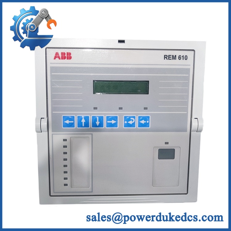
ABB REM610 Relion 610
Module 4: Dynamic Emergency Swap & Configuration Guide
1. Pre-Swap Prep — Capture the Protection Settings First
Put the motor protection scheme into the plant’s approved maintenance state and isolate the relevant control and auxiliary supplies. Record the complete REM610 ordering code from the nameplate, because REM610 alone does not identify the CT or auxiliary-voltage variant. Back up protection settings, motor FLA, startup limits, thermal parameters, trip logic, digital-input configuration, communication settings, and event records. Photograph terminal wiring and the existing relay position.
2. Removal — Use the Plug-In Construction to Your Advantage
uses a removable plug-in relay design, which ABB specifically notes as facilitating commissioning and fast insertion/removal of the relay unit. After isolation and zero-voltage verification, release the relay’s mechanical retention mechanism and withdraw the plug-in unit from its case. Do not disturb the fixed case wiring or force the unit if a retaining mechanism remains engaged. Protect the withdrawn relay from ESD and mechanical impact.
3. Installation & Configuration — Match CT and Supply Variant
Insert the replacement into the existing case and secure it according to the installation procedure. Before energization, compare the replacement ordering code with the original unit. CT rating is especially important: ABB specifies separate 1 A and 5 A energizing-input versions, with different thermal and dynamic current withstand capabilities. Confirm the auxiliary supply as well; the relay family includes both high-voltage and 24/48/60 VDC supply variants. Restore the complete protection parameter set rather than relying on factory defaults.
4. Power-On Self-Test (POST) — Validate Protection Logic, Not Just Startup
Energize the relay under controlled conditions and verify normal startup without internal-relay-fault indication. Confirm the HMI is operational, measured phase currents are plausible, and all configured inputs and outputs report correctly. Then perform functional checks for applicable trip and alarm stages. The can process phase-current measurements from 0 to 50 × In and ground-fault measurements from 0 to 8 × In, so the commissioning test should exercise the configured protection elements using an approved secondary-injection setup.
Module 5: Quality Assurance & Testing SOP
Each should receive a serialized inspection and controlled protection-relay test before shipment.
- OEM anti-counterfeit visual inspection: Check ABB branding, identification, labels, connector interfaces, housing construction, display, keys, indicator windows, and PCB workmanship.
- Exact variant verification: Record the complete ordering code, especially the 1 A / 5 A CT rating and auxiliary-voltage configuration.
- Mechanical inspection: Check the plug-in housing, terminal interfaces, locking mechanism, display, keypad, enclosure, and signs of corrosion, impact, contamination, or unauthorized repair.
- Power-input verification: Confirm the test source matches the relay’s exact auxiliary-supply version. ABB documents both high-voltage and low-voltage supply variants.
- Power-on self-test (POST): Energize the IED and verify startup diagnostics, display operation, status indications, and internal-relay-fault monitoring.
- Current-input test: Apply calibrated secondary current to the applicable phase inputs and verify measurement accuracy and channel identification.
- I/O full-range simulation: Exercise digital inputs, trip outputs, alarm outputs, IRF signaling, and other configured binary functions.
- Thermal-overload simulation: Test the 49 thermal model using approved current-injection values and verify alarm, restart-inhibit, and trip behavior against the configured settings. ABB documents the thermal model as a key protection function.
- Overcurrent test: Verify phase overcurrent pickup and operating logic against the stored settings.
- Earth-fault test: Simulate ground-fault current and verify the applicable pickup, timing, alarm, and trip functions.
- Startup and stall simulation: Where applicable, test cumulative motor-startup supervision and running-stall protection.
- Communication test: Verify the configured communication interface and protocol when the installed variant includes that option. ABB lists IEC 61850, IEC 60870-5-103, Modbus, Profibus, SPA, and LON among supported communication protocols for the family.
- Extended stability test: Monitor relay operation under energized conditions for intermittent faults, display abnormalities, unexpected resets, or thermal issues.
- Final QC record: Record serial number, complete type code, CT rating, auxiliary supply, firmware/configuration information, test currents, operating times, alarm results, photographs, technician sign-off, and packaging condition.
Module 6: Maintenance & Reliability FAQ
1. Is ABB a direct drop-in replacement, or does it require a firmware flash?
is a complete motor protection relay, but the word “” alone is insufficient for a safe replacement decision. The exact ordering code determines key hardware characteristics such as CT input rating and auxiliary supply. ABB documents both 1 A and 5 A CT versions and multiple auxiliary-power configurations. A firmware update should not be assumed simply because a replacement relay is installed; restore and verify the required configuration using the applicable ABB service procedure.
2. Is it safe to hot-swap while the system is running?
The relay uses a plug-in design, but that does not automatically make it electrically safe to remove under load. ABB describes the plug-in construction as facilitating insertion and withdrawal during commissioning and maintenance, but the plant-specific protection and switching procedure still governs live replacement. Unless the applicable documentation explicitly authorizes energized extraction, isolate the relay and associated circuits before removal.
3. Will replacing cause my current protection settings to be lost?
The replacement relay should not be assumed to contain the site’s existing motor-protection settings. Back up the complete configuration before removal, including motor FLA, thermal model parameters, startup supervision, stall settings, phase/earth-fault thresholds, output logic, digital inputs, communication parameters, and any RTD configuration. The thermal algorithm in depends on configured motor and environmental parameters, so factory defaults are not a suitable substitute for the plant’s validated settings.
4. What should I verify before commissioning the replacement?
First verify the complete type code, not merely the front-panel “” marking. Then confirm the CT rating, auxiliary supply, frequency, wiring, protection settings, communications, and optional RTD arrangement. ABB specifies 1 A or 5 A CT inputs, 50/60 Hz ±5 Hz operation, and phase-current measurement up to 50 × In. The replacement should then pass secondary-injection and I/O functional testing before the motor is returned to service.
5. What are the warranty terms if the unit fails after installation?
Warranty coverage should be stated on the quotation or sales order for the specific serialized relay. Retain the incoming inspection report, nameplate photographs, configuration backup, secondary-injection results, I/O test records, and commissioning report. For a protection relay, those records are important because an apparent relay failure can also originate from incorrect CT wiring, auxiliary supply mismatch, configuration errors, or external trip-circuit problems.











 Start Chat


