

Description
- Brand: ABB
- Full Model Number: REM610C55HCNN02
- Product Family: Relion REM610 / 610 Series
- Lifecycle Status: Legacy product; replacement availability requires exact variant verification
- Core Function in System: Motor protection, measurement, supervision, and control for asynchronous motors
- Top 3 Hardcore Specs: Thermal overload protection; earth-fault protection; loss-of-phase / phase-unbalance protection
- Protection Scope: Medium and large LV asynchronous motors; small and medium HV asynchronous motors
- Communication Options: IEC 61850, IEC 60870-5-103, Modbus, Profibus, SPA, LON, depending on configuration
- Construction: Removable plug-in protection relay
- Temperature Monitoring: Optional RTD/thermistor functionality depending on configuration
- Condition & Lead Time: Replacement stock subject to exact suffix and hardware verification; emergency dispatch based on confirmed inventory
Module 3: Technical Intro & Downtime Impact
When a motor protection relay fails, the motor may remain mechanically healthy while the protection and control chain prevents a safe restart. ABB REM610C55HCNN02 belongs to the REM610 family and is designed for protection, measurement, supervision, and control of asynchronous motors. Its protection functions cover conditions such as thermal overload, excessive starting duration, running stall, earth fault, and phase loss or phase unbalance.
For MTTR reduction, the removable plug-in construction is a practical advantage. The relay can be withdrawn from its dedicated case instead of requiring removal of the complete protection assembly. Depending on the configuration, the 610-series platform supports multiple station-bus and communication interfaces, while optional temperature inputs can monitor critical motor points. Exact auxiliary voltage, CT ratio, communication variant, and temperature-input configuration must be confirmed from the relay nameplate and project documentation before replacement. —Do not treat another REM610 variant as automatically equivalent.
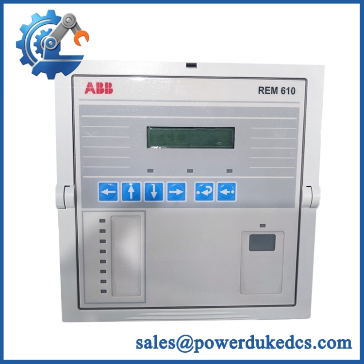
ABB REM610C55HCNN02
Module 4: Dynamic Emergency Swap & Configuration Guide
1. Pre-Swap Prep — Preserve the protection settings
- Place the motor feeder in the approved maintenance state.
- Apply site lockout/tagout.
- Verify absence of hazardous voltage with the approved test instrument.
- Record REM610C55HCNN02, hardware revision, serial number, and communication configuration.
- Back up or document the complete relay settings.
- Photograph the front panel, case, terminals, and external wiring.
- Record motor full-load current, thermal settings, start supervision, earth-fault settings, and trip logic.
- Use ESD protection before handling the relay.
2. Removal — Use the plug-in relay construction
- Confirm the feeder and associated auxiliary circuits are in the required safe state.
- Follow the REM610 withdrawal procedure for the installed case.
- Operate the relay’s release and pull-out mechanism.
- Withdraw the relay straight from its case.
- Avoid applying force to the connector or front-panel controls.
- Inspect the mating connector and case for bent contacts, corrosion, contamination, or heat damage.
3. Installation & Configuration — Match the original protection package
- Verify ABB REM610C55HCNN02 before installation.
- Confirm hardware revision and communication option.
- Check that the replacement is compatible with the existing relay case.
- Insert the relay evenly until fully seated.
- Engage the retaining mechanism.
- Restore the documented protection settings.
- Verify CT configuration, motor rated current, thermal model, start supervision, earth-fault settings, and phase-loss protection.
- Restore communication parameters and addresses where applicable.
- Reconfigure RTD or thermistor inputs if fitted.
- Do not use factory defaults as the final commissioning configuration.
4. Power-On Self-Test (POST) — Verify protection before starting
- Reapply auxiliary power using the approved switchgear procedure.
- Observe the display and status indicators during initialization.
- Confirm self-supervision reports no persistent internal fault.
- Verify displayed current and measured values against known system values.
- Check binary input/output states and trip-circuit supervision.
- Verify communication with the protection or control system where applicable.
- Confirm all restored protection settings.
- Perform the prescribed secondary-injection or functional test before starting the motor.
- Conduct a controlled motor start only after protection checks are complete.
Module 5: Quality Assurance & Testing SOP
A replacement REM610 should pass hardware inspection, electrical screening, configuration verification, and protection-function testing before shipment. A relay that simply powers up is not sufficient evidence of readiness.
1. OEM identity verification
- Verify ABB
- Verify REM610C55HCNN02
- Confirm REM610 / Relion 610 Series identification
- Compare front-panel markings, case coding, connector arrangement, and hardware revision
- Perform OEM anti-counterfeit visual inspection
- Photograph identification and revision markings
2. Mechanical inspection
- Inspect the plug-in housing for cracks, deformation, contamination, and impact damage
- Check the pull-out handle and release mechanism
- Inspect plug-in contacts for bent, recessed, oxidized, or contaminated pins
- Verify correct seating in the mating case
- Inspect the case and mounting arrangement
3. Electrical screening
- Verify auxiliary-power input according to the exact ordering variant
- Check protective-earth continuity where applicable
- Inspect binary input/output circuits
- Verify CT input integrity using an appropriate secondary-injection setup
- Inspect terminal and connector condition
- Do not apply arbitrary hipot or insulation-test voltages directly to populated electronic circuitry
4. Functional testing
- Perform power-on self-test
- Check RUN/READY and ERR or equivalent diagnostic indications
- Verify internal self-supervision
- Perform secondary current injection
- Test configured overcurrent protection stages
- Test earth-fault protection
- Test thermal overload behavior
- Test phase-loss or phase-unbalance protection where configured
- Test motor-start supervision
- Test stall protection where configured
- Verify trip outputs
- Verify trip-circuit supervision
- Check event and disturbance recording
- Test configured communication interfaces
- Perform I/O full-range simulation on applicable inputs and outputs
- Record injected values, pickup thresholds, time delays, firmware revision, and final results
5. Final QC release
- Independent QC sign-off
- Complete settings backup retained with the test record
- ESD-safe packaging
- Mechanical protection for the relay and connector
- Final identification check of REM610C55HCNN02
- Inspection photographs retained
- Functional-test report retained with shipment records
Module 6: Maintenance & Reliability FAQ
Q1. Is ABB a direct drop-in replacement, or does it require a firmware flash?
The plug-in construction simplifies physical replacement, but the relay should still be treated as a configuration-controlled spare. Verify the complete ordering code, hardware revision, communication option, and installed protection configuration. Firmware should only be changed when the applicable ABB documentation requires a specific revision.
Q2. Is it safe to hot-swap the while the system is running?
Do not assume that it is. Although the relay has a plug-in construction, live withdrawal can affect protection availability and may expose personnel to hazardous circuits. Follow the exact switchgear maintenance procedure and use an approved isolation or protection-bypass procedure where required.
Q3. Will replacing the cause my current program or configuration to be lost?
The important settings are the protection parameters, measurement scaling, trip logic, communication configuration, motor thermal model, and optional temperature-monitoring configuration. Back up or document the complete setting file before replacement. After installation, restore the verified settings and compare the relay readings with the pre-failure baseline before starting the motor.
Q4. What motor faults can the protect against?
The family is intended for asynchronous motor protection and can provide functions including thermal overload, motor-start supervision, running-stall protection, earth-fault protection, and phase-loss or phase-unbalance protection. Depending on the installed configuration, temperature monitoring can also be implemented through RTD or thermistor inputs.
Q5. What should I verify before ordering a replacement?
Verify the complete ordering code first. Then check the hardware revision, auxiliary supply, CT input characteristics, communication option, relay-case compatibility, protection settings, and any RTD or thermistor option. For an emergency replacement, photographs of the existing nameplate and front panel should be compared with the replacement before installation.











 Start Chat


