

Description
- Brand: ABB
- Full Model Number: REM620E-1G
- Product Series: Relion 620 Series
- Product Type: Motor Protection and Control Relay
- Lifecycle Status: Established installed-base protection platform
- Core Function in System: Protection, control, measurement, and supervision of medium and large asynchronous or synchronous motors
- Top 3 Hardcore Specs: 2.0 FP1 product version; IEC 61850 / Modbus / DNP3 support; withdrawable plug-in design
- Auxiliary Supply: Configuration-dependent; 24–60 VDC or 48–250 VDC / 100–240 VAC
- Binary Inputs: 24–250 VDC rated; 16–176 VDC selectable threshold
- Binary Input Reaction: <3 ms
- Operating Temperature: -25 to +55 °C continuous
- Communication: IEC 61850, IEC 61850-9-2 LE, Modbus, IEC 60870-5-103, DNP3
- Dimensions: 246 × 160 × 201 mm case
- Weight: Maximum 5.1 kg complete relay; maximum 3.0 kg plug-in unit
- Condition & Lead Time: Tested inventory or factory-sealed stock; emergency dispatch subject to confirmed availability
ABB identifies REM620 as a dedicated motor management relay in the Relion 620 family, designed for protection, control, measurement, and supervision of medium-sized and large asynchronous and synchronous motors. The 620 platform uses a withdrawable-unit design and supports multiple station communication protocols.
Module 3: Technical Intro & Downtime Impact
A motor protection relay failure can remove critical protection and control functions at exactly the wrong time. Trip logic, current and voltage supervision, thermal protection, breaker control, measurements, and communications may all be affected. ABB REM620E-1G belongs to the Relion 620 motor protection and control family, intended for medium and large motors where protection and operational supervision have to remain available.
The hardware specification is configuration-dependent, so the installed ordering code matters. ABB documents auxiliary supply variants covering 24–60 VDC and 48–250 VDC / 100–240 VAC; binary inputs are rated for 24–250 VDC, with selectable thresholds from 16–176 VDC and reaction time below 3 ms. Continuous operation is specified from -25 to +55 °C, while communication options include Ethernet, RS-232/RS-485, fiber interfaces, IEC 61850, Modbus, IEC 60870-5-103, and DNP3.
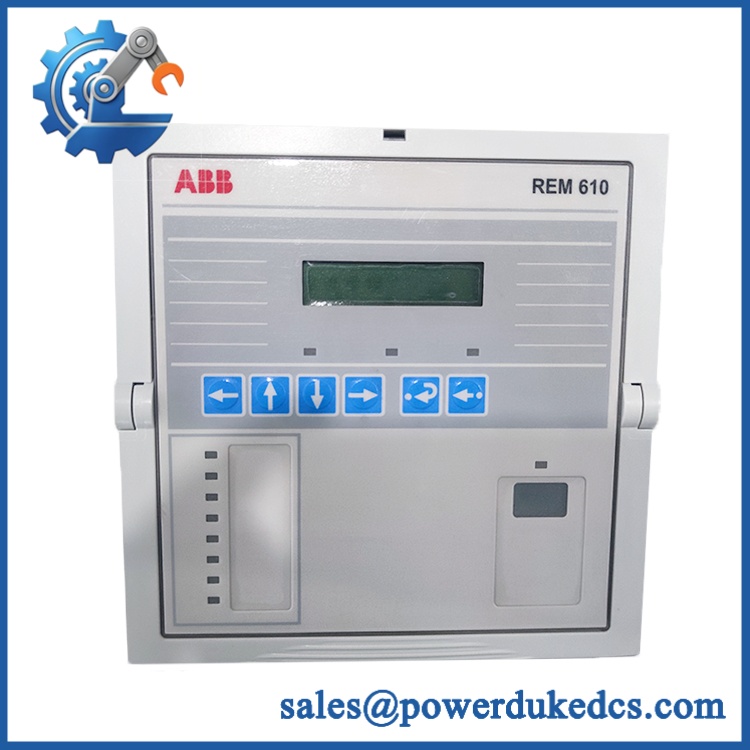
ABB REM620E-1G
Module 4: Dynamic Emergency Swap & Configuration Guide
1. Pre-Swap Prep — capture the exact relay configuration
Place the motor feeder in the plant-approved maintenance state and follow the site’s LOTO procedure. Before removal, photograph the REM620E-1G front panel, terminal wiring, LED conditions, nameplate, and relay position. Record the complete ordering code, auxiliary supply type, CT/VT input arrangement, binary I/O configuration, communication interface, protection settings, and PCM600 configuration. Confirm whether the installation uses conventional instrument transformers or sensor inputs.
2. Removal — use the withdrawable-unit architecture correctly
The REM620 uses a withdrawable plug-in design. After approved isolation, disconnect or secure external wiring according to the cabinet procedure, release the relay’s mechanical retention, and withdraw the plug-in unit straight from its case. Do not pull against terminal wiring or force the unit at an angle. Inspect the case connectors and mating contacts for contamination, oxidation, loose terminals, or heat damage before inserting the spare. ABB specifies a maximum plug-in-unit weight of 3.0 kg.
3. Installation & Configuration — match supply, I/O, and communication options
Insert the replacement into the original case and secure the mechanical retention. Confirm that the auxiliary supply variant matches the installed relay before energizing. Reconnect CT/VT circuits, binary inputs, outputs, communications, and time-synchronization wiring according to the approved connection diagram. Restore the validated protection and control configuration through PCM600, including protection settings, signal matrices, communication parameters, and logic. Hardware options are not interchangeable by appearance alone.
4. Power-On Self-Test (POST) — validate protection before closing the breaker
Apply auxiliary power and monitor the relay’s startup and self-supervision indications. Confirm that the LHMI initializes normally with no persistent diagnostic alarm. Verify current and voltage measurements, binary-input states, output operation, breaker status, trip-circuit supervision, and station communication. Test representative protection elements under a controlled commissioning procedure before permitting the motor feeder to return to service. ABB documents self-supervision, disturbance recording, event logging, and condition-monitoring functions for REM620.
Module 5: Quality Assurance & Testing SOP
The REM620E-1G should undergo relay-specific verification rather than a generic controller inspection.
- OEM Anti-Counterfeit Visual Inspection: Verify ABB and Relion markings, REM620E-1G designation, nameplate data, case construction, connector geometry, front-panel controls, and hardware revision.
- Serial and Identity Traceability: Record serial number, complete ordering code, hardware revision, and nameplate photographs.
- Mechanical Inspection: Examine the withdrawable plug-in unit, case, guides, retainers, terminal blocks, and connector contacts.
- Auxiliary Power Verification: Test the installed supply variant under controlled conditions; do not apply an assumed supply voltage.
- Power-On Self-Test (POST): Record startup behavior, self-supervision status, diagnostic messages, and all available status LEDs.
- Measurement Verification: Inject controlled current and voltage signals and verify measured values against calibrated test equipment.
- Binary Input Test: Simulate applicable DC input states across the documented operating range and verify state recognition and reaction timing.
- Binary Output Test: Command each required output and verify electrical state, contact operation, and assigned logic.
- Protection Function Test: Validate applicable motor protection elements, trip logic, alarms, blocking signals, and supervision functions.
- Communication Test: Verify the installed interface and applicable protocol, including IEC 61850, Modbus, DNP3, or IEC 60870-5-103 as configured.
- Time Synchronization Test: Check IEEE 1588, SNTP, or IRIG-B where included in the installed configuration.
- Disturbance and Event Recording Test: Confirm event logs and disturbance records are created correctly during controlled test events.
- Extended Powered Test: Monitor the relay for unstable communications, unexpected resets, diagnostic alarms, or abnormal temperature.
- Final QC Record: Release only after test measurements, configuration records, serial traceability, photographs, and QC approval are complete.
ABB specifies a maximum complete-relay weight of 5.1 kg, a case size of 246 × 160 × 201 mm, and continuous operating temperature of -25 to +55 °C. For units equipped with an LC communication interface, ABB states a maximum operating temperature of +70 °C.
Module 6: Maintenance & Reliability FAQ
1. Is the REM620E-1G a direct drop-in replacement, or does it require a firmware flash?
The 1G designation identifies product version 2.0 FP1, but complete compatibility still depends on the full ordering code and hardware configuration. ABB’s ordering structure includes communication, HMI, protection-option, and power-supply selections. Verify the complete installed ordering code and firmware before treating the replacement as a direct substitute.
2. Is it safe to hot-swap the while the system is running?
Do not assume that the withdrawable construction makes live removal acceptable. The relay is mechanically withdrawable, but energized removal depends on the particular switchgear arrangement, wiring, and approved maintenance procedure. Unless the equipment documentation explicitly permits live withdrawal, isolate the feeder and auxiliary supply first.
3. Will replacing this relay cause my current protection program to be lost?
The safest procedure is to back up the complete PCM600 project, protection settings, application configuration, signal matrix, communication parameters, disturbance records where required, and the exact hardware ordering code. The replacement relay should not be assumed to contain the site’s active protection configuration. ABB notes that end users create application configurations using the configuration functionality of PCM600.
4. What should I verify after installing the replacement?
Check auxiliary supply compatibility first. Then verify CT/VT measurements, binary I/O, trip outputs, breaker position, trip-circuit supervision, protection settings, communication links, event logging, and time synchronization. For a motor feeder, perform the approved secondary-injection or functional protection test before energizing the motor.
5. What are the warranty terms if the unit fails post-installation?
Warranty coverage should be tied to the supplied serial number and documented stock condition. The commercial terms should clearly distinguish hardware defects from failures caused by incorrect CT/VT wiring, improper auxiliary voltage, configuration errors, installation damage, ESD, or unauthorized modification. The exact warranty period and return procedure should be confirmed before purchase.











 Start Chat


