

Description
- Brand: ABB
- Full Model Number: RET615E-1G
- Product Family: Relion RET615 615 Series
- Lifecycle Status: Established 615-series protection platform; exact hardware, configuration, and firmware revision require verification
- Core Function in System: Transformer protection, control, measurement, and supervision for two-winding power transformers
- Top 3 Hardcore Specs: 50/60 Hz ±5 Hz | 1 A or 5 A rated current inputs | 100–240 VAC or 24–250 VDC auxiliary supply depending on hardware type
- Protection Functions: Transformer differential 87T | Restricted earth-fault protection | Overcurrent and ground-fault protection | Thermal protection | Circuit-breaker failure protection
- Communications: IEC 61850 | IEC 61850-9-2 LE | Modbus | DNP3
- Physical Format: Withdrawable plug-in protection relay; 4U frame
- Condition & Lead Time: New or surplus inventory subject to exact configuration verification; expedited dispatch available for stocked units
ABB identifies RET615 as a dedicated transformer protection and control relay for power transformers, including two-winding and generator-transformer applications. The product family uses a compact withdrawable-unit design and supports IEC 61850, Modbus, and DNP3 communications.
Module 3: Technical Intro & Downtime Impact
When a transformer protection relay fails, the consequence is not simply a lost display. Protection, trip logic, measurements, alarms, and breaker-control functions can become unavailable, potentially keeping an otherwise serviceable transformer offline until the protection channel is restored. The ABB RET615E-1G belongs to the Relion 615 family and is designed specifically for transformer protection and control. Its supported functions include stabilized transformer differential protection, restricted earth-fault protection, overcurrent, ground-fault, thermal, undervoltage/overvoltage, and circuit-breaker failure protection.
For MTTR planning, configuration matching matters more than the front-panel appearance. ABB specifies 1 A or 5 A rated current inputs, 60–210 V AC voltage inputs, and auxiliary power variants covering 100–240 V AC or 24–250 V DC, depending on the hardware type. The relay accepts up to 20 A continuously on its current inputs and 500 A for 1 second under the specified thermal withstand condition. Physical dimensions are approximately 177 mm × 177 mm × 201 mm, with a complete relay weight of 4.1 kg and plug-in unit weight of 2.1 kg. Continuous operating temperature is -25 to +55 °C. These figures are useful during an emergency exchange because they expose mismatches before the replacement is energized.
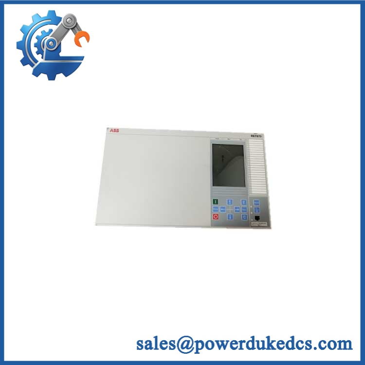
ABB RET615E-1G
Module 4: Dynamic Emergency Swap & Configuration Guide
1. Pre-Swap Prep — Freeze the Existing Protection Configuration
At a protection-relay failure, first preserve the configuration before touching the hardware. Apply the plant’s approved LOTO procedure and isolate the relay circuits as required by the switchgear design. Record the existing RET615E-1G ordering code, firmware/application revision, CT ratios, VT ratios, protection settings, binary I/O assignments, communication parameters, and station address. Back up the relay configuration through the approved ABB engineering workflow where possible. Keep the original terminal drawing beside the work area.
2. Removal — Withdraw the Plug-In Unit
The RET615 uses a withdrawable plug-in design, not a DIN-rail installation. After the circuit has been made safe, disconnect or isolate the relevant wiring according to the switchgear manufacturer’s procedure. Release the relay’s mechanical retention hardware and withdraw the plug-in unit straight from the case. Do not force the assembly if the extraction path is obstructed; terminal alignment and the rear connector arrangement must remain controlled. ABB specifies separate dimensions for the complete relay and the plug-in unit.
3. Installation & Configuration — Match Hardware Before Settings
Insert the replacement RET615 plug-in unit into the original case and secure it using the specified retention method. Verify the auxiliary supply type before energization: ABB provides both AC and DC supply variants. Check CT and VT input ratings, communication interface type, I/O population, and optional functions against the original relay. IEC 61850 communication, for example, depends on the installed communication hardware and configuration.
A field note: RET615E-1G is not sufficient by itself to establish every hardware option. The complete order code and configuration must be compared before treating the replacement as equivalent.
4. Power-On Self-Test (POST) — Check Relay Health Before Any Trip Test
Apply auxiliary power only after confirming polarity, voltage range, and terminal integrity. Observe the local HMI and alarm/status indications for a normal startup. Confirm that self-supervision reports no active internal fault, then verify measured current and voltage channels against known secondary values. Check station communication, event reporting, binary inputs, trip outputs, and interlocking logic before returning the transformer to service. ABB documents self-supervision, alarm LED viewing, event handling, and signal monitoring through the relay’s engineering environment.
Module 5: Quality Assurance & Testing SOP
Every available ABB RET615E-1G should pass a controlled inspection sequence before shipment:
- OEM anti-counterfeit visual inspection — verify ABB markings, RET615 identification, product labels, case condition, connectors, HMI, terminal hardware, and manufacturing markings.
- Part-number reconciliation — compare the physical relay against RET615E-1G and the customer’s complete order code rather than relying only on the family name.
- Configuration verification — record firmware revision, application configuration, CT/VT ratios, communication settings, binary I/O mapping, and option hardware.
- Auxiliary power test — verify the actual relay supply type before applying controlled voltage. ABB specifies AC and DC variants with defined operating ranges.
- Power-on self-test (POST) checking for ERR/status indications — verify normal startup, HMI operation, self-supervision status, alarm indications, and event recording.
- Current-input simulation — inject representative secondary current signals at appropriate levels and verify measured phase and residual currents.
- Voltage-input simulation — apply controlled voltage signals within the specified 60–210 V AC input range and verify measurement accuracy and correct phase relationships.
- I/O full-range simulation — exercise available binary inputs, binary outputs, analog/RTD channels where fitted, and protection-related control signals according to the installed configuration. ABB’s I/O matrix varies by standard configuration and option code.
- Protection-function verification — simulate appropriate fault conditions for differential, overcurrent, earth-fault, thermal, voltage, and breaker-failure functions supported by the specific configuration.
- Communication test — verify the installed interface using the customer’s intended protocol such as IEC 61850, Modbus, or DNP3. Fiber interfaces may use LC or ST connections depending on the installed hardware.
- Final QA record — retain label photographs, configuration records, test measurements, communication results, alarm/event checks, and packaging inspection.
ABB’s published technical data also specifies a 50 ms maximum interruption time on the auxiliary DC supply without relay reset, providing a useful reference during power-quality verification.
Module 6: Maintenance & Reliability FAQ
Is the ABB a direct drop-in replacement, or does it require a firmware flash?
A physically matching can replace an existing relay of the same configuration, but the complete hardware and software configuration must match. RET615 supports configurable signal matrices and application logic through PCM600, and ABB specifies multiple standard configurations and optional hardware. A replacement with different I/O or firmware/application characteristics should not be treated as a blind drop-in swap.
Is it safe to hot-swap the while the system is running?
Do not assume energized withdrawal is acceptable. The is withdrawable, but the safety of removing the plug-in unit depends on the switchgear design, isolation arrangement, CT circuits, VT circuits, and approved maintenance procedure. CT circuits in particular require correct handling before disconnecting protection equipment. Follow the site switching and LOTO procedure and the applicable ABB/switchgear documentation.
Will replacing this protection relay cause my current settings or protection logic to be lost?
Replacing the physical relay does not automatically recreate the original protection settings. The replacement unit needs the correct application configuration, signal matrix, protection parameters, CT/VT ratios, I/O assignments, communication settings, and logic. ABB provides PCM600 functions for saving relay parameter settings and transferring configuration data.
Maintain a current configuration backup before an outage. That is the most effective way to prevent a hardware replacement from becoming a settings-recovery exercise.
What should I verify when matching an spare?
Verify the complete ordering code, not just “.” Check auxiliary supply type, current-input rating, voltage-input arrangement, binary I/O count, communication hardware, optical interface type, standard configuration, firmware/application version, and any RTD or arc-protection options. ABB’s documentation shows that I/O and communication capabilities vary with the selected hardware and configuration.
What are the warranty terms if the relay fails after installation?
Warranty is determined by the supplying party and the purchase agreement. Confirm the coverage period, DOA terms, return procedure, and exclusions before shipment. Keep the pre-shipment inspection record, relay identification photographs, configuration record, and commissioning test results. For a protection relay, that evidence is particularly valuable when separating a defective unit from CT/VT wiring, auxiliary-power, configuration, or communications faults.











 Start Chat


