

Description
- Brand: ABB
- Full Model Number: RTD0003 / 2RCA027422A0001
- Lifecycle Status: Active catalog spare; stocked at selected ABB distribution locations
- Core Function in System: Temperature and analog signal acquisition for ABB Relion 620-series protection and control relays
- Top 3 Hardcore Specs: 6 RTD sensor inputs; 2 generic mA inputs; X105 slot installation
- Supported Relay Family: REF620 / REM620 / RET620 and other compatible 620-series configurations
- Signal Type: RTD + mA
- Condition & Lead Time: New OEM spare; availability should be confirmed against current stock before emergency release
ABB’s technical documentation specifies RTD0003 as an optional card for 620-series devices, providing 2 generic mA inputs and 6 RTD sensor inputs in slot X105.
Module 3: Technical Intro & Downtime Impact
A failed temperature-input card can do more than remove a few measurements. In a protection or condition-monitoring application, loss of RTD feedback can disable temperature-based supervision, generate persistent alarms, or force the maintenance team to operate with reduced instrumentation. ABB RTD0003, part 2RCA027422A0001, is the dedicated RTD/mA input card used with compatible Relion 620-series protection and control devices. ABB specifies six RTD sensor inputs plus two generic mA inputs, giving one compact acquisition interface for temperature and process signals.
For MTTR, the key advantage is straightforward card-level replacement. The RTD0003 occupies the designated X105 position, while the field connections are defined through the corresponding ABB connection diagram. The documented terminal map assigns RTD channels to six separate input pairs and provides two mA input pairs, with common RTD ground terminals also identified. Do not infer sensor type or wiring from terminal appearance alone; Pt100, other RTD characteristics, shielding, and transmitter wiring must match the relay configuration and site drawings.
Module 4: Dynamic Emergency Swap & Configuration Guide
1. Pre-Swap Prep — Protect the Relay and Preserve the Existing Wiring
Place the affected protection relay in the maintenance state required by the site procedure. Isolate control power where required, and use an ESD wrist strap before opening the relay enclosure. Photograph the existing RTD0003 position, terminal wiring, shielding arrangement, and relay configuration. Have the ABB installation manual, calibrated multimeter, small screwdriver, and the original card available for comparison.
2. Removal — Release the X105 Card Carefully
The RTD0003 is a plug-in card associated with the X105 position. Remove the external wiring according to the approved isolation procedure, then release the card retention hardware and withdraw the card without forcing the connector interface. Keep wires identified by channel; swapping RTD pairs can create incorrect temperature readings without necessarily producing an immediate hardware fault.
3. Installation & Configuration — Match the Exact Channel Map
Install the replacement / 2RCA027422A0001 into the X105 position and secure it correctly. ABB’s connection diagram assigns mA 1 to terminals 5–6, mA 2 to 7–8, RTD 1 to 9–10, RTD 2 to 11–12, RTD 3 to 13–14, RTD 4 to 17–18, RTD 5 to 19–20, and RTD 6 to 21–22, with common RTD ground terminals at 15–16. Reproduce the original wiring and shielding arrangement exactly.
4. Power-On Self-Test (POST) — Verify Every Measurement Path
Restore power and confirm the relay completes its normal startup diagnostics without hardware alarms. Check that the card is recognized, then validate each connected RTD and mA channel. For RTDs, compare the displayed temperature against a known reference or controlled simulator. For mA inputs, inject representative low-, mid-, and high-range signals. A clean startup alone is insufficient; every safety- or protection-relevant channel should be functionally verified before the relay returns to service.
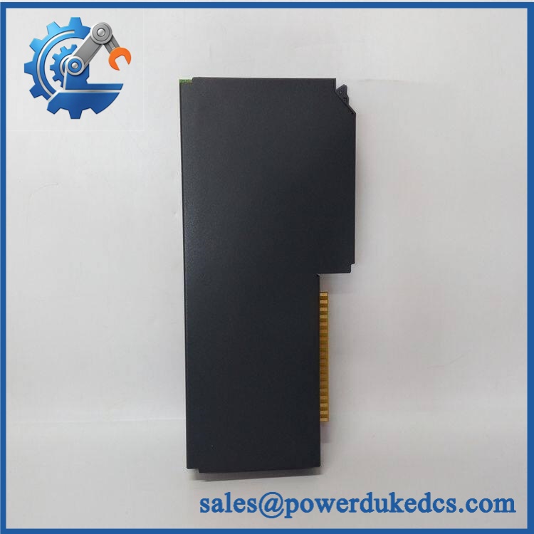
ABB RTD0003 2RCA027422A0001
Module 5: Quality Assurance & Testing SOP
The / 2RCA027422A0001 should be tested as a precision signal-acquisition card, not merely given a visual power-up check.
- Identity verification: Record ABB part number, designation, 2RCA027422A0001 identification, revision markings, and serial information.
- OEM anti-counterfeit visual inspection: Examine PCB markings, labels, connectors, board finish, mounting hardware, and manufacturing identifiers against known ABB construction.
- Mechanical inspection: Check connector condition, card guides, retention hardware, edge contacts, contamination, corrosion, and signs of thermal stress.
- Power-on self-test (POST): Install the card in an approved compatible test environment and verify normal relay startup diagnostics and expected status behavior.
- RTD full-range simulation: Exercise all required RTD channels with suitable calibrated resistance/RTD simulation equipment and verify that the relay reports the expected temperature response.
- mA full-range simulation: Test both generic mA inputs through representative low, midpoint, and upper-range values.
- Channel mapping verification: Confirm that each physical input corresponds to the expected software channel and that no two channels have been transposed.
- Ground and shielding inspection: Verify the RTD common-ground arrangement and cable shielding against the applicable ABB wiring diagram. ABB recommends screened RTD/mA instrument cabling for this interface.
- Extended powered test: Monitor the card during a controlled run for intermittent readings, abnormal heating, communication faults, or diagnostic changes.
- Final QC record: Retain identification photographs, measured values, test fixture details, test date, and technician sign-off.
ABB documentation confirms the configuration as 6 RTD + 2 mA for the 620-series architecture.
Module 6: Maintenance & Reliability FAQ
1. Is ABB a direct drop-in replacement, or does it require a firmware flash?
The / 2RCA027422A0001 is an I/O acquisition card rather than the main application processor. A routine user-program firmware transfer should not be assumed. The critical checks are the exact card identification, compatible 620-series relay configuration, position, hardware revision, and channel configuration. ABB’s documentation identifies as an optional card for compatible 620-series configurations.
2. Is it safe to hot-swap this card while the system is running?
Do not assume hot-swap capability. The connects directly into the relay’s internal card position, and live removal should only be performed where the exact relay model and ABB procedure explicitly permit it. For a protection relay in service, controlled isolation is the safer maintenance practice.
3. Will replacing this card cause my current protection settings or program to be lost?
Replacing the does not normally erase the main relay application because the card provides the physical RTD/mA acquisition interface rather than serving as the primary application storage device. Still, export or back up the relay configuration before intervention. Record RTD type, scaling, channel assignments, alarm limits, and any engineering parameters that depend on these measurements.
4. How do I verify that the replacement card is reading temperature correctly?
Do not rely only on a healthy relay startup indication. Inject known RTD values with a calibrated simulator and compare the relay’s displayed temperature against the expected result. Then verify the complete signal path through the protection or monitoring logic. For mA channels, use a calibrated current source and test multiple points across the configured range.
5. What are the warranty terms if the unit fails post-installation?
For supplied replacement stock, the warranty should be tied to the exact condition and sales quotation. Retain the serial number, incoming inspection record, pre-shipment test results, installation date, and post-installation measurements. That evidence helps distinguish a defective from field wiring errors, incorrect sensor configuration, or an issue elsewhere in the relay.











 Start Chat


