

Description
- Brand: ABB
- Full Model Number: RTU560
- Product Family: ABB RTU500 Series
- Product Type: Remote Terminal Unit
- Core Function in System: Remote monitoring, control, data acquisition, protocol conversion, and substation automation
- Supported Data Points: Up to 5,000 for RTU560 platform
- IEC 61850: Client and server / proxy functions available depending on configuration
- Host Protocols: IEC 60870-5-101/102/103/104 | Modbus | DNP3 | SPA
- Control Logic: IEC 61131 PLC functionality
- Architecture: Rack-mounted and DIN-rail configurations available
- Communication Capacity: Up to 8 communication modules in RTU560 rack architecture
- Condition & Lead Time: Stock condition subject to inspection; emergency dispatch available subject to order confirmation
ABB identifies RTU560 as part of the RTU500 series and supports applications including substation automation, remote monitoring, control, and communications. ABB documentation states that the RTU560 platform can support up to 5,000 data points, while its architecture provides IEC 61850 gateway/server functions and flexible communication interfaces depending on the selected hardware.
Module 3: Technical Intro & Downtime Impact
A remote terminal unit failure can isolate an entire substation or remote industrial site from the control center. The field devices may continue operating locally, yet SCADA loses telemetry, alarms, remote commands, or protocol conversion. ABB RTU560 serves as the communications and automation layer between field I/O, intelligent electronic devices, local control functions, and higher-level control systems. ABB documentation lists support for IEC 60870-5-101/102/103/104, Modbus, SPA, and DNP3, with IEC 61850 capabilities depending on the selected configuration.
For MTTR, the should be treated as a configured system rather than a single universal hardware item. The platform is available in different chassis, central processing, I/O, power-supply, and communication configurations. An older RTU560E implementation, for example, uses a 560CMU80 CPU, supports up to four local Multi I/O cards and up to 27 decentralized I/O cards through an extension bus, with optional Ethernet and multiple serial interfaces. This means the exact CMU, PSU, I/O, communications cards, firmware release, and configuration files must be identified before ordering a replacement.
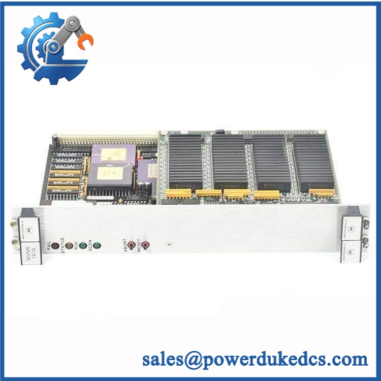
ABB RTU560
Module 4: Dynamic Emergency Swap & Configuration Guide
1. Pre-Swap Prep — Freeze the RTU Configuration Before Power Down
Put the affected RTU into the plant’s approved maintenance state and isolate the appropriate power sources. Export the current RTU configuration, PLC application, communication parameters, I/O mapping, protocol settings, and firmware information before removing hardware. Record the rack or DIN-rail architecture, slot positions, CMU identification, PSU type, communication-card part numbers, and every active field link. Keep an offline copy of the configuration file.
2. Removal — Identify the Architecture Before Pulling Hardware
is not a single fixed form factor. ABB documents both rack-based systems and DIN-rail implementations, with separate CMU, I/O, communication, and auxiliary modules. For a rack system, isolate power, disconnect field and communications wiring as required, release the module retention mechanism, and withdraw only the failed board. For a DIN-rail assembly, release the rail latch after all connectors have been safely disconnected. Do not remove a neighboring communication or I/O card merely to gain access unless the applicable hardware procedure requires it.
3. Installation & Configuration — Rebuild the Original Hardware Topology
Install the replacement in the same physical position and hardware role. Match the CMU, power supply, I/O modules, communication modules, and bus connections against the recorded configuration. Do not replace a communication card based solely on connector appearance; installations can use different serial, Ethernet, modem, and optical interfaces.
Restore the saved configuration and verify the assigned protocol for every communications channel. Older RTU560E documentation, for example, lists two RS-232 interfaces, one RS-485 interface, and optional 10Base-T Ethernet on the 560CMU80, while communication support includes IEC 60870-5 protocols, Modbus, SPA, and DNP3.0. The exact installed hardware must determine which interfaces are commissioned.
4. Power-On Self-Test (POST) — Validate the Data Path End to End
Power the RTU under controlled conditions and inspect the CPU/CMU status, power indicators, communication status, and system alarms. Confirm that the configuration loads without errors and that each expected I/O module is detected.
Then test the actual control path: field input → RTU processing → protocol communication → SCADA, followed by the reverse command path where permitted. Check timestamps, quality flags, event reporting, counters, and communication diagnostics. A healthy CPU LED is only the first checkpoint. The repair is incomplete until the control center receives valid process data and authorized remote commands operate correctly.
Module 5: Quality Assurance & Testing SOP
Every replacement should be tested as a configured automation system, not merely powered on at the bench.
- OEM anti-counterfeit visual inspection: Verify ABB markings, type labels, PCB identification, connector construction, terminal geometry, and manufacturing quality.
- Exact hardware verification: Identify the installed CMU, PSU, I/O, communication modules, chassis, and revision levels before release.
- Mechanical inspection: Check rack connectors, DIN-rail latches where applicable, mounting hardware, backplane interfaces, terminal blocks, fiber interfaces, and signs of corrosion or unauthorized repair.
- Power-supply verification: Apply only the input voltage specified for the actual PSU. installations use multiple power-supply variants; an label alone does not determine the PSU rating.
- Power-on self-test (POST): Verify system startup, processor diagnostics, power status, module recognition, and alarm behavior.
- I/O full-range simulation: Exercise the applicable binary inputs, binary outputs, analog inputs/outputs, counters, and process signals across the approved operating ranges.
- Communication-interface test: Test every installed serial, Ethernet, optical, or modem interface against its configured protocol.
- Protocol simulation: Verify applicable IEC 60870-5-101/102/103/104, Modbus, SPA, DNP3, and IEC 61850 functions against the actual project configuration.
- PLC application test: Where IEC 61131 logic is deployed, load the approved application and verify execution, interlocks, timers, counters, and defined outputs.
- Redundancy test: Where the installed design uses redundant processing or power, simulate the primary-path failure and confirm the intended standby behavior.
- End-to-end SCADA test: Verify telemetry, quality flags, timestamps, alarms, SOE/event reporting, and remote control commands.
- Extended stability test: Monitor the RTU under sustained communication and I/O activity for resets, watchdog events, communication retries, module dropouts, and abnormal temperature.
- Final QC record: Record all module part numbers, firmware versions, configuration checksum/version, I/O results, protocol tests, alarm results, photographs, technician sign-off, and packaging condition.
Module 6: Maintenance & Reliability FAQ
1. Is ABB a direct drop-in replacement, or does it require a firmware flash?
is a platform family, not one universal hardware part number. A safe replacement requires the exact installed architecture to be identified first: CMU/CPU, PSU, I/O cards, communication cards, chassis, firmware, and project configuration. ABB’s architecture is modular, with different rack and DIN-rail configurations. A firmware update should only be performed when the replacement hardware and project documentation require it.
2. Is it safe to hot-swap an module while the system is running?
Do not assume that every card is hot-swappable. The answer depends on the exact hardware assembly and the applicable ABB service documentation. Power supplies, CPU/CMU units, communication cards, and I/O modules can have different replacement procedures. For an emergency field repair, use the documented isolation procedure unless live replacement is explicitly supported for the exact hardware.
3. Will replacing cause my current program or configuration to be lost?
A replacement CPU or communication assembly should not be expected to contain the site’s current project configuration automatically. Back up the RTU configuration, PLC application, protocol parameters, I/O mappings, communication addresses, and firmware information before shutdown. ABB also documents RTU500 configuration and firmware file handling as part of its fleet-management functions.
4. What should I verify before commissioning an replacement?
Start with the exact hardware inventory, not the generic name. Confirm the CMU, PSU, rack or DIN-rail chassis, I/O cards, communication interfaces, firmware release, protocol configuration, and project file. Then perform I/O simulation and end-to-end SCADA testing. This is particularly important because ABB’s platform supports materially different hardware architectures and communication combinations.
5. What are the warranty terms if the unit fails after installation?
Warranty coverage should be defined on the quotation or sales order for the specific serialized hardware. Retain module photographs, part-number records, firmware information, configuration backups, I/O test results, protocol diagnostics, and commissioning reports. For systems, this documentation is particularly valuable when separating a failed hardware component from a configuration, protocol, network, or field-I/O fault.











 Start Chat


