

Description
MBrand: ABB
- Full Model Number: S200-IE8 / 200-IE8
- Product Series: Advant S200 I/O
- Lifecycle Status: Active S200 I/O product family
- Core Function in System: 8-channel analog signal acquisition for ABB Satt DCS and related S200 I/O systems
- Top 3 Hardcore Specs: 8 single-ended inputs; 12-bit resolution; 0/4–20 mA and 0/2–10 VDC / ±10 VDC
- Input Resistance: 200 kΩ voltage; 238 Ω current
- Galvanic Isolation: Yes, via optocouplers; eight inputs isolated as a group from the serial bus
- Filter: First-order low-pass; 100 ms time constant
- Accuracy: ±0.2% FS at 25 °C
- Non-Linearity: ≤0.10% current; ≤0.05% voltage
- Status Indicator: Green PWR LED
- Terminal Base: 200-TB3 preferred; 200-TB3S and 200-TB2 compatible
- Condition & Lead Time: Tested inventory or factory-sealed stock; emergency dispatch subject to confirmed availability
ABB identifies the 200-IE8 as an 8-channel analog input unit in the S200 I/O family. It accepts 0/4–20 mA, 0/2–10 VDC, and ±10 VDC, uses 12-bit conversion, and provides group galvanic isolation through optocouplers. ABB also states that S200 I/O can be retained when evolving a Satt system toward System 800xA.
Module 3: Technical Intro & Downtime Impact
A failed analog input unit can quietly corrupt an entire group of process measurements. Flow, pressure, level, temperature, position, or other transmitter values may freeze, drift, or disappear, leaving control logic with bad process data rather than an obvious controller failure. ABB -IE8 / 200-IE8 provides eight single-ended analog inputs for the I/O platform, with selectable voltage or current input ranges and group galvanic isolation from the serial bus.
For maintenance planning, the useful numbers are concrete: 12-bit resolution, 100 ms first-order filtering, ±0.2% FS accuracy at 25 °C, and input resistance of 200 kΩ for voltage or 238 Ω for current. Current signals can be 0–20 mA or 4–20 mA; voltage signals can be 0–10 VDC, 2–10 VDC, or ±10 VDC. These characteristics make channel verification straightforward during commissioning—provided the replacement, terminal base, transmitter range, and software configuration all match the original installation.
Module 4: Dynamic Emergency Swap & Configuration Guide
1. Pre-Swap Prep — verify the signal architecture first
Put the affected process section into the plant-approved maintenance state and follow the site’s LOTO procedure where required. Before touching the unit, photograph the -IE8 label, PWR LED, terminal wiring, terminal-base designation, and module position. Record each channel’s transmitter type, 0/4–20 mA or voltage range, engineering range, and software channel assignment. Keep an ESD wrist strap available. ABB specifies the 200-TB3 as the preferred terminal base, with 200-TB3S and 200-TB2 also compatible.
2. Removal — use the modular construction correctly
ABB states that I/O supports replacement under system power, but live replacement should still follow the plant’s approved maintenance procedure and the exact installed configuration. Release the module from its mounting arrangement, withdraw it without twisting the terminal-base connection, and protect the field wiring from movement. Do not disconnect individual transmitter wires unless the maintenance procedure requires it; keeping the terminal base and field wiring undisturbed reduces reconnection errors.
3. Installation & Configuration — match every analog channel
Insert the replacement -IE8 into the existing terminal base and secure it mechanically. Confirm that the module is seated correctly and that the terminal-base hardware matches the installation. Verify every software channel’s configured signal type: 0–20 mA, 4–20 mA, 0–10 VDC, 2–10 VDC, or ±10 VDC. The analog range cannot be assumed from the transmitter label alone; check the DCS configuration and original loop documentation before applying process power.
4. Power-On Self-Test (POST) — prove measurements, not just module power
After restoration, confirm the green PWR indicator illuminates normally. Check that the host I/O system recognizes the unit without diagnostic faults. Using calibrated loop simulation, inject known current and voltage values on representative channels and compare the returned engineering values with the configured range. Test low, mid-scale, and high-scale points, then restore field transmitters and confirm stable process values. The module’s published 100 ms filter means immediate step changes should not be judged as instantaneous readings.
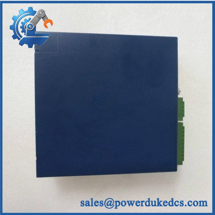
ABB S200-IE8 200-IE8
Module 5: Quality Assurance & Testing SOP
The -IE8 is an analog measurement device, so the acceptance test should focus on signal accuracy, range selection, and isolation.
- OEM Anti-Counterfeit Visual Inspection: Verify ABB markings, -IE8 / 200-IE8 designation, enclosure shape, terminal arrangement, labels, connector geometry, and revision markings.
- Serial and Identity Traceability: Record the unit identification and photograph the complete product label before testing.
- Mechanical Inspection: Examine the housing, terminal interface, mounting features, PCB edges, and mating surfaces for impact or corrosion damage.
- Power Verification: Apply the approved supply and verify normal startup behavior.
- Power-On Self-Test (POST): Confirm the green PWR LED illuminates correctly and remains stable.
- Analog Input Range Test: Verify operation with calibrated 0–20 mA, 4–20 mA, 0–10 VDC, 2–10 VDC, and ±10 VDC test signals as applicable.
- Full-Range Simulation: Check representative low-scale, mid-scale, and full-scale points on all eight channels where the laboratory setup permits.
- Accuracy Verification: Compare readings with calibrated equipment against the specified ±0.2% FS at 25 °C baseline.
- Resolution Check: Verify expected 12-bit conversion behavior during controlled signal changes.
- Filter Response Test: Apply a controlled step input and verify expected first-order filtering behavior with the specified 100 ms time constant.
- Channel Isolation Test: Confirm the analog input group remains properly isolated from the serial bus and that stimulation of one channel does not create unintended changes elsewhere.
- Input Resistance Check: Verify approximately 200 kΩ on voltage input paths and 238 Ω on current input paths where applicable.
- Extended Powered Test: Monitor all channels for drift, intermittent readings, unexpected resets, or unstable values.
- Final QC Record: Store calibration results, channel-by-channel measurements, identification photographs, test equipment references, and QC approval with the unit.
ABB describes the I/O family as software-configurable and mechanically coded for safer replacement. The company also states that I/O supports replacement under system power and can remain in place during an evolution toward System 800xA.
Module 6: Maintenance & Reliability FAQ
1.the a direct drop-in replacement, or does it require a firmware flash?
For the same installation and compatible hardware configuration, the 200-IE8 is intended as an I/O unit rather than a general-purpose controller requiring a firmware migration. The critical checks are the exact I/O position, terminal base, channel configuration, and software signal range. ABB identifies the 200-IE8 as an 8-channel analog input unit with software-configurable voltage/current operation.
2. Is it safe to hot-swap this module while the system is running?
ABB states that the I/O system supports replacement under system power. That does not eliminate site-specific electrical hazards, however. Follow the cabinet’s approved live-maintenance procedure, confirm that the process state permits module replacement, and use appropriate ESD controls before withdrawing the unit.
3. Will replacing this analog input unit cause my current program to be lost?
Replacthe itself does not constitute replacing the DCS application. The practical risk is configuration mismatch. Back up the Satt/DCS project, I/O configuration, channel ranges, scaling, alarm limits, and terminal documentation before intervention. Then verify the restored channel configuration after installing the spare.
4. What should I test after installing the replacement?
Start with the PWR indication and system diagnostics. Then verify each configured channel using calibrated 4–20 mA or voltage simulation as applicable. Check low, mid-scale, and high-scale values, engineering-unit conversion, alarm thresholds, and communication to the host control system. For a critical transmitter loop, compare the controller value against a calibrated source before returning the process to automatic control.
5. What are the warranty terms if the unit fails post-installation?
Warranty coverage should be tied to the supplied unit’s identification and documented condition, whether factory-sealed, tested, or refurbished. Hardware defects under specified operating conditions should be covered, while incorrect wiring, overvoltage, ESD damage, transmitter faults, configuration errors, and unauthorized modification should be treated separately. The exact warranty period and return process should be stated on the quotation before purchase.











 Start Chat


