

Description
- Brand: ABB
- Full Model Number: SDCS-PIN-4B
- Product Family: DCS800 DC Drives
- Product Type: Power Supply and Interface Board
- Lifecycle Status: Legacy DCS800 installed-base component
- Core Function in System: Drive power supply distribution, armature bridge control, voltage/current measurement, and field-exciter interface
- Top 3 Hardcore Specs: 115/230 VAC auxiliary supply; 120 VA consumption; 3-phase controlled field-exciter interface up to 25 A DC on D4
- Auxiliary Supply: 115 VAC or 230 VAC; 230 VDC supported on SDCS-PIN-4B
- Supply Tolerance: -15% / +10%
- Supply Frequency: 45–65 Hz for AC input
- Power Loss: ≤60 W
- Inrush Current: 10 A / 20 ms
- Recommended Fuse: 6 AT
- Field Exciter AC Range: 110–525 VAC
- Field Exciter Insulation Voltage: 600 VAC
- Field Exciter Frequency: 50/60 Hz
- Minimum Field Current: 300 mA
- Onboard Field Exciter Output: 6 A D1, 15 A D2, 20 A D3, 25 A D4
- Condition & Lead Time: Tested inventory or factory-sealed stock; emergency dispatch subject to confirmed availability
ABB documents the SDCS-PIN-4 / SDCS-PIN-4B as an interface board for DCS800 converter sizes D1 through D4+, combining the drive power supply function with armature control/measurement and, on applicable D1–D4 units, the onboard field-exciter interface. The SDCS-PIN-4B automatically adapts between 115 VAC and 230 VAC auxiliary supply and also supports 230 VDC auxiliary input.
Module 3: Technical Intro & Downtime Impact
A failed SDCS-PIN-4B can produce a drive-level outage rather than a simple control-board alarm. The board supplies low-voltage power to the DCS800 control system and connected options, interfaces with the armature bridge, handles high-impedance DC/AC voltage measurement, and amplifies firing pulses. On D1–D4 converters, it also interfaces with the onboard field exciter and measures field current. A fault here can therefore affect drive startup, armature regulation, field excitation, and measurement integrity at the same time.
The electrical limits are particularly important during a replacement. The SDCS-PIN-4B accepts 115 VAC or 230 VAC, with -15%/+10% tolerance; 230 VDC is also supported on the 4B version. ABB specifies 120 VA consumption, ≤60 W power loss, and a 10 A / 20 ms inrush current for the AC supply. Its onboard field-exciter circuit is rated for 110–525 VAC, with DC output ratings of 6 A, 15 A, 20 A, and 25 A for D1, D2, D3, and D4 respectively. Correct jumper and supply configuration matters—particularly where an unstable 230 VAC source could otherwise cause the wrong voltage-detection behavior.
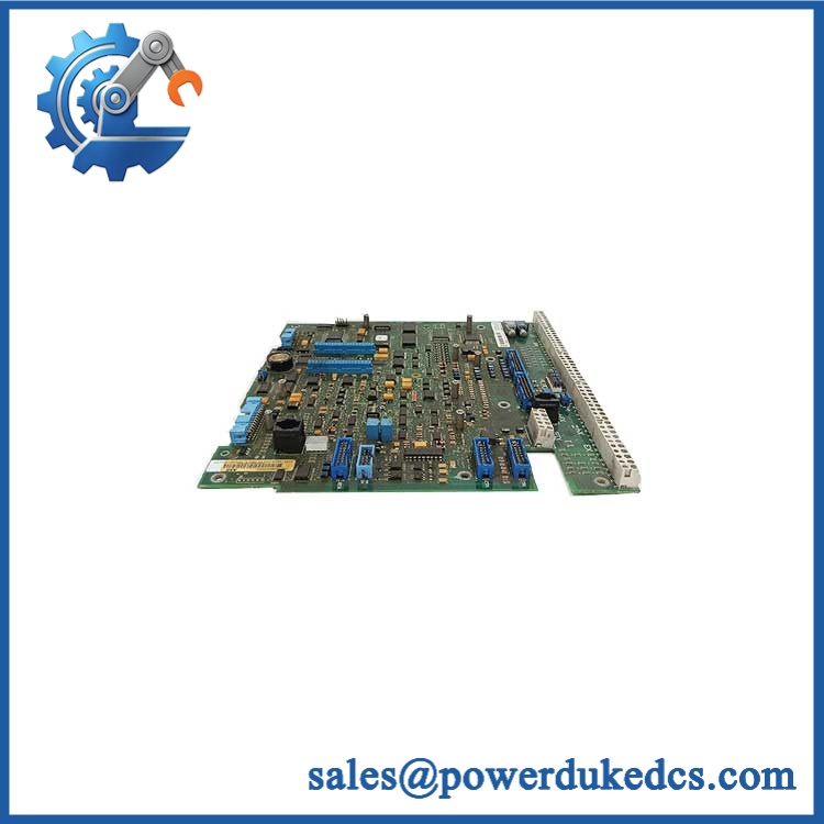
ABB SDCS-PIN-4B
Module 4: Dynamic Emergency Swap & Configuration Guide
1. Pre-Swap Prep — treat the board as a high-voltage drive component
Place the DCS800 drive in the approved maintenance condition and complete full LOTO. ABB explicitly warns that qualified electricians must perform installation and maintenance and that main and control circuits can retain hazardous voltages. Verify with a properly rated multimeter that the input phases and DC bus are at approximately 0 V before proceeding. Record the existing wiring, jumper position, auxiliary supply type, DCS800 converter size, and field-current configuration. Use an ESD wrist strap when handling the PCB.
2. Removal — disconnect the board without disturbing power hardware
After voltage absence has been verified, photograph connector locations and the existing PCB layout. Disconnect the relevant X-connectors and wiring according to the schematic, including the auxiliary supply, armature interface, field-current measurement, and firing-pulse connections where fitted. Remove the board from its mounting position without flexing the PCB. Inspect fuses, connectors, screw terminals, and nearby power components for heat damage before installing the spare. The is integrated into the drive’s power and control architecture, so a burned connector can be the original fault rather than a symptom.
3. Installation & Configuration — match the supply and jumper state exactly
Install the replacement in the same mechanical position and reconnect every interface against the original wiring diagram. Confirm the auxiliary supply before energization. ABB documents automatic detection of 115 VAC or 230 VAC as the default condition, while the corresponding jumper configuration can fix operation to 230 VAC where required. For applications using the onboard field exciter, verify the converter size and field-circuit requirements before reconnecting the field wiring. Never infer jumper position from another cabinet.
4. Power-On Self-Test (POST) — validate the complete converter path
Energize the drive only after all safety checks are complete. Observe the controller’s startup and diagnostic indications, then confirm auxiliary voltages, armature voltage measurement, armature current feedback, firing-pulse generation, and field-current measurement. Where the onboard field exciter is used, verify the field circuit under a controlled test condition before enabling the motor. Check the diagnostic system for persistent hardware or measurement faults. ABB identifies the as part of the armature and field interfaces, so a simple control-power check is not sufficient acceptance evidence.
Module 5: Quality Assurance & Testing SOP
The requires board-level electrical inspection followed by controlled converter-interface testing.
- OEM Anti-Counterfeit Visual Inspection: Verify ABB markings, identification, connector arrangement, component placement, fuses, transformers, relays, and revision markings against a verified reference.
- Serial and Identity Traceability: Photograph the complete board identification and record serial/revision information where present.
- Mechanical Inspection: Check PCB edges, mounting hardware, terminals, connectors, fuse holders, and signs of contamination or thermal damage.
- Auxiliary Supply Verification: Test 115 VAC, 230 VAC, and 230 VDC capability where applicable to the specific 4B configuration.
- Supply Tolerance Check: Verify expected operation across the documented -15%/+10% auxiliary supply tolerance.
- Power-On Self-Test (POST): Energize under controlled conditions and check all accessible status and fault indications.
- Power Consumption Test: Monitor startup and steady-state consumption against the documented 120 VA baseline where the laboratory arrangement permits.
- Inrush Verification: Check startup behavior against the documented 10 A / 20 ms inrush characteristic.
- Armature Measurement Test: Inject controlled measurement signals and verify the armature current and AC/DC voltage measurement circuits.
- Firing Pulse Test: Verify firing-pulse generation and distribution to the applicable thyristor bridge interfaces.
- Field Circuit Test: For D1–D4 applications using the onboard field exciter, validate controlled field output and field-current measurement.
- Field Exciter Range Verification: Confirm the test setup is within the documented 110–525 VAC input range and applicable current rating.
- Relay Output Test: Verify the isolated X96 relay output where fitted; ABB specifies up to 250 VAC / 3 A, 24 VDC / 3 A, or 115/230 VDC / 0.3 A depending on the application.
- Protection Inspection: Verify fuses and overvoltage-protection components before final release.
- Extended Powered Test: Monitor the board for intermittent resets, abnormal heating, unstable auxiliary supply behavior, or field-current measurement drift.
- Final QC Record: Document part identification, jumper configuration, measured supply values, electrical test results, photographs, and QC approval.
ABB specifies that the ‘s auxiliary input can automatically accommodate 115 VAC or 230 VAC, while its power section includes filtering, voltage limitation, fusing, and relay-output circuitry. The board also contains the amplification stage for field firing pulses and interfaces directly with the power section.
Module 6: Maintenance & Reliability FAQ
1. Is the a direct drop-in replacement, or does it require a firmware flash?
This board is primarily a hardware interface and power board, not the main application controller. A firmware flash is therefore not normally the central replacement issue. The critical checks are the exact board version, converter size, wiring, auxiliary-supply configuration, jumper state, and field-exciter arrangement. Verify those items against the installed configuration before energization.
2. Is it safe to hot-swap the while the drive is running?
No. This is a power-interface board connected to hazardous AC and DC circuits. ABB’s safety instructions state that maintenance personnel must ensure the input phases and DC bus are approximately 0 V before working on the drive, and that control circuits can also contain dangerous externally supplied voltages.
3. Will replacing the cause my current drive program to be lost?
Replacing this board is not equivalent to replacing the control board. The application resides in the drive control system, while the provides power and hardware-interface functions. Even so, back up the complete parameters and application configuration before intervention. Record the existing measurement, field-exciter, and jumper configuration so the replacement reproduces the original hardware state.
4. What should I test after installing the replacement?
Verify auxiliary supply first, including correct 115/230 VAC configuration. Then check armature voltage and current measurements, firing pulses, field-current feedback, relay outputs, and all relevant diagnostics. For an onboard field exciter, confirm the field-current response under a controlled commissioning test before applying normal motor load.
5. What are the warranty terms if the unit fails post-installation?
Warranty coverage should be tied to the supplied board’s serial number and documented condition. Hardware failure under the specified operating conditions should be distinguishable from damage caused by incorrect supply voltage, incorrect jumper configuration, wiring faults, overvoltage, ESD, or downstream power-device failures. The exact warranty period and return procedure should be stated on the quotation before purchase.











 Start Chat


