

Description
- Brand: ABB
- Full Model Number: SDCS-POW-4 / 3ADT315100R1001
- ABB Type Designation: SDCS-POW-4-COAT
- Lifecycle Status: No longer for sale by ABB; replacement-stock item
- Core Function in System: Auxiliary power generation for DCS800 converter electronics
- Top 3 Hardcore Specs: 115/230 VAC auto-detect | 45–65 Hz | 120 VA power consumption
- Output Function: Internal DC supply generation for SDCS-CON-4 and connected electronic boards
- Compatible Hardware: DCS800 D5, D6 and D7 converter modules
- Encoder Supply: Selectable 5 V, 12 V, 15 V or 24 V; maximum 250 mA
- Input Protection: Recommended 6 AT fuse; 30 ms minimum mains buffering at 115 VAC and 300 ms at 230 VAC
- Physical Board Size: Approximately 220 × 110 mm
- Condition & Lead Time: New, refurbished, or surplus inventory subject to exact revision and stock verification; expedited dispatch for stocked units
ABB’s DCS800 hardware documentation identifies 3ADT315100R1001 as the SDCS-POW-4 power supply board, designed for D5–D7 converter modules. The board automatically accepts either 115 VAC or 230 VAC auxiliary supply and generates the DC voltages required by the SDCS-CON-4 and other electronic boards. ABB’s product data also identifies the current designation as SDCS-POW-4-COAT and marks the product as no longer for sale.
Module 3: Technical Intro & Downtime Impact
A DCS800 converter can remain mechanically intact while a failed auxiliary power board takes its control electronics offline. When that happens, the SDCS-CON-4 and associated electronic boards no longer receive the required internal DC rails, leaving the converter unable to perform normal control functions. The ABB SDCS-POW-4 3ADT315100R1001 is specifically designed for DCS800 D5, D6, and D7 converter modules and is mounted on the electronic tray. ABB describes it as a switched-mode flyback power supply that generates the necessary DC voltages for the control board and other electronics.
For MTTR planning, the important values are unusually clear. The auxiliary input is automatically detected between 115 VAC and 230 VAC, with a 45–65 Hz frequency range, -15%/+10% tolerance, and approximately 120 VA power consumption. ABB specifies a maximum power loss of 60 W and a recommended 6 AT input fuse. The board also supplies selectable encoder voltage of 5, 12, 15, or 24 V, limited to 250 mA. Those settings matter during replacement: an incorrect encoder-supply jumper arrangement can create a secondary commissioning fault even when the replacement board itself is healthy.
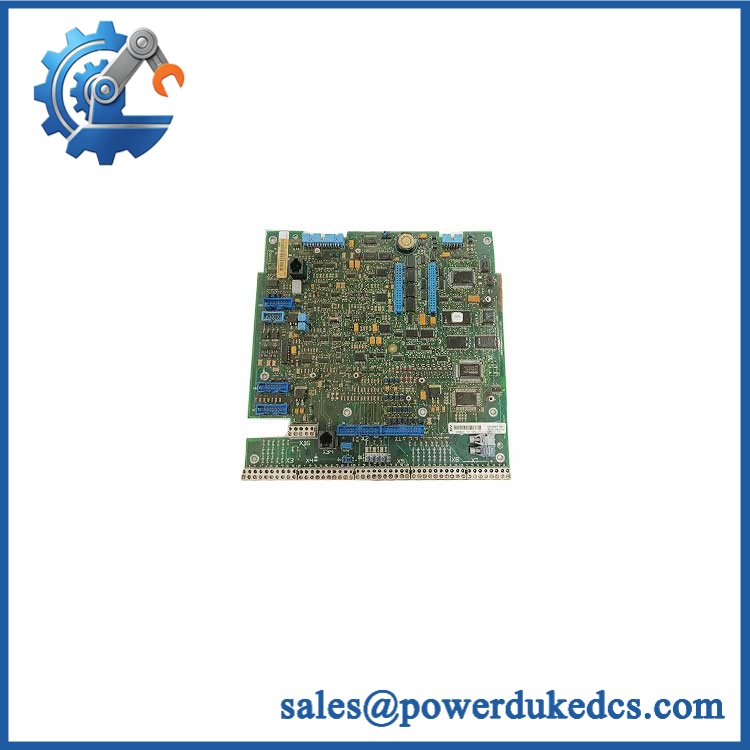
ABB SDCS-POW-4 3ADT315100R1001
Module 4: Dynamic Emergency Swap & Configuration Guide
1. Pre-Swap Prep — Isolate the DCS800 and Document Jumper Settings
This board carries hazardous auxiliary AC. Apply the plant’s approved LOTO procedure and verify the absence of voltage before opening the converter. Record the original board identification, AC wiring at X99, flat-cable connections at X37/X137, hard-parallel connection at X14 where used, and the settings of S3, S4, and S5.
Also photograph the encoder-supply jumper arrangement before removal. ABB specifies selectable encoder supplies of 5 V, 12 V, 15 V, or 24 V, and the choice depends on the installed encoder and control-board configuration.
2. Removal — Disconnect the Electronic-Tray Board
After proving the auxiliary supply is dead, disconnect the AC input at X99 and the associated low-voltage/flat-cable connections. Remove the board from its electronic-tray mounting arrangement while supporting the PCB to prevent connector or board flex.
Do not treat SDCS-POW-4 like a DIN-rail power supply. The ABB technical drawing shows a PCB approximately 220 × 110 mm, with X99, X96, X37/X137, X14, and the S3/S4/S5 jumper area distributed across the board.
3. Installation & Configuration — Match the Original Power and Encoder Setup
Install / 3ADT315100R1001 in the original electronic-tray position. Reconnect X37 or X137 to the SDCS-CON-4 using the original flat-cable route. If a hard-parallel converter is fitted, restore X14 exactly as documented. ABB states that X37 and X137 are connected in parallel, while X14 is used for hard-parallel converter connections.
Before energizing, duplicate the original S3/S4/S5 encoder-voltage settings. The jumper table provides different combinations for 5 V, 12 V, 15 V, and 24 V operation. A field note: 3ADT315100R1001 is the coated version, so confirm that the replacement’s coating and revision are suitable for the original cabinet environment. ABB’s product record identifies it as .
4. Power-On Self-Test (POST) — Verify Internal Rails and Startup
Restore the auxiliary AC under controlled conditions and verify the input is within the specified range before loading the converter electronics. Check for abnormal fuse operation, excessive heat, unusual switching noise, or odor.
Then verify the SDCS-CON-4 starts normally and that the control system recognizes the converter without power-supply-related faults. Where encoder feedback is installed, confirm the encoder receives the intended supply voltage and that speed feedback is stable. Verify DO8 at X96 where the relay output is used; ABB documents this as an isolated normally open relay contact controlled by digital output 8.
Module 5: Quality Assurance & Testing SOP
Each available ABB / 3ADT315100R1001 should undergo a controlled inspection and electrical acceptance sequence before shipment:
- OEM anti-counterfeit visual inspection — verify ABB markings, designation, 3ADT315100R1001 identification, coating, PCB construction, connectors, terminals, and manufacturing markings.
- Part-number reconciliation — compare the physical board with the customer’s BOM and confirm the required COAT version.
- Revision inspection — record PCB revision, date code, component condition, connector condition, and evidence of unauthorized repair.
- Jumper verification — document S3, S4, and S5 settings and compare them with the customer’s encoder requirements.
- Insulation and grounding tests — perform appropriate safety tests using procedures and test levels suitable for the board and laboratory equipment.
- Controlled AC input test — apply 115 VAC and/or 230 VAC as appropriate through an isolated, protected laboratory source. ABB specifies automatic input detection between the two nominal voltages.
- Power-on self-test (POST) — verify stable startup and absence of abnormal protective behavior while monitoring the generated internal DC rails.
- Load test — apply a controlled representative electronic load while monitoring input current, output stability, thermal rise, and abnormal switching behavior.
- Encoder supply test — verify the selected 5/12/15/24 V encoder supply and confirm current capability does not exceed the documented 250 mA limit.
- DO8 relay verification — where the test fixture supports it, verify the isolated normally open relay output at X96. ABB specifies contact ratings of up to 250 VAC / 3 A or 24 VDC / 3 A, with reduced current limits at higher DC voltages.
- Control-board communication test — confirm proper power delivery to a compatible SDCS-CON-4 test assembly through X37/X137.
- functional simulation — where a complete test rack is available, verify converter control startup, diagnostics, encoder feedback, and relevant digital-output behavior.
- Thermal observation — monitor the board during sustained operation. ABB specifies up to 60 W power loss, making cabinet ventilation and thermal condition relevant during long-duration testing.
- Final QA record — retain label photographs, jumper settings, measured input values, internal-rail measurements, load results, thermal observations, and final packaging photographs.
The is not a simple fixed-output 24 VDC supply. Its output rails serve several internal functions, while the encoder supply is configurable. Testing should therefore reproduce the actual board configuration rather than checking only whether the PCB powers up.
Module 6: Maintenance & Reliability FAQ
Is the ABB 3ADT315100R1001 a direct drop-in replacement?
It is the correct replacement family for D5, D6, and D7 applications when the original board is the same configuration. ABB identifies 3ADT315100R1001 as the coated power-supply board. Verify the complete part number, PCB revision, coating, jumper settings, connector arrangement, and cabinet configuration before installation.
Does the require a firmware flash?
No firmware flash is normally the primary replacement operation for the power-supply board itself. The critical configuration items are hardware-related, especially the S3/S4/S5 encoder-supply selection and the physical connections to and associated options. The function of the X96/DO8 relay output is controlled through the firmware parameters rather than by loading application firmware onto the power-supply board.
Is it safe to hot-swap the while the is running?
No. The receives 115/230 VAC auxiliary power, and the board is part of the converter’s internal electronic supply system. ABB’s hardware documentation requires appropriate electrical isolation before service. Disconnecting it while energized can expose personnel to hazardous voltage and can abruptly remove power from the control electronics.
Will replacing the cause my current program to be lost?
The is a power-supply board rather than the main control board. Replacing it does not normally erase the control-board application by itself. Nevertheless, preserve the parameter set, application configuration, encoder settings, and any customized control data before maintenance. The replacement must restore the same hardware configuration so the existing control system starts with the expected supply and feedback conditions.
What should I verify before ordering an emergency spare?
Confirm , 3ADT315100R1001, the COAT designation, the frame/module size, encoder-supply setting, and whether the installation uses hard-parallel converters through X14. ABB states that the board is intended for D5–D7 modules and automatically accommodates 115 VAC or 230 VAC auxiliary input. Also confirm the PCB revision from the existing spare before purchase.
What are the warranty terms if the board fails after installation?
Warranty depends on the supplying party and the purchased stock condition. Confirm the warranty duration, DOA coverage, testing scope, and return procedure before shipment. Retain the pre-shipment QA record, jumper photographs, measured AC input, internal power-rail results, and commissioning data. Those records are particularly useful for separating an failure from a downstream short, incorrect encoder-voltage selection, or a fault in the connected .











 Start Chat


