

Description
- Brand: ABB
- Full Model Number: SPCIS22
- Product Series: HR Series I/O
- Product Type: Control I/O Module
- Lifecycle Status: Legacy ABB Symphony/HR Series installed-base component
- Core Function in System: Mixed analog and digital process input/output interface
- Top 3 Hardcore Specs: 4 analog inputs; 3 digital inputs; 4 digital outputs + 2 analog outputs
- Analog Inputs: 4 × 4–20 mA independently configured
- Analog Outputs: 2 × 4–20 mA independently configured
- Digital Inputs: 3 optically isolated channels
- Digital Outputs: 4 optically isolated open-collector channels
- Logic Supply: +5 VDC ±5%
- Additional Supplies: +15 VDC and -15 VDC
- Termination Supply: +24 VDC ±10%
- Ambient Temperature: 0 to +70 °C / +32 to +158 °F
- Key Integration: IEMMU mounting units with NFTP01 / NTCS04 termination hardware
- Response Profile: Standard control-I/O response; SPQRS22 provides approximately 10× faster response
- Condition & Lead Time: Tested inventory or factory-sealed stock; emergency dispatch subject to confirmed availability
ABB identifies SPCIS22 and SPQRS22 as HR Series control I/O modules. The two are functionally equivalent, but ABB states that SPQRS22 provides approximately ten times faster response while offering lower noise rejection. SPCIS22 provides 3 optically isolated digital inputs, 4 optically isolated open-collector digital outputs, 4 independently configured 4–20 mA analog inputs, and 2 independently configured 4–20 mA analog outputs.
Module 3: Technical Intro & Downtime Impact
A failed SPCIS22 can remove several signal types from service at the same time. One board may carry analog measurements, discrete status signals, control outputs, and 4–20 mA commands, so a single hardware fault can create a cluster of process alarms rather than one isolated channel failure. ABB places the SPCIS22 in the HR Series I/O architecture, where it serves as a control I/O interface between field signals and the process-control system.
The electrical architecture is clearly defined: +5 VDC ±5%, +15 VDC, -15 VDC, and +24 VDC ±10% from the termination unit. ABB specifies 100 mA typical / 180 mA maximum at +5 V, 27 mA typical / 35 mA maximum at +15 V, 23 mA typical / 30 mA maximum at -15 V, and 46 mA typical / 65 mA maximum at +24 V. Ambient operation is 0 to +70 °C. During emergency maintenance, those figures matter because an incorrect termination-unit supply or damaged interface can make a good replacement appear defective.
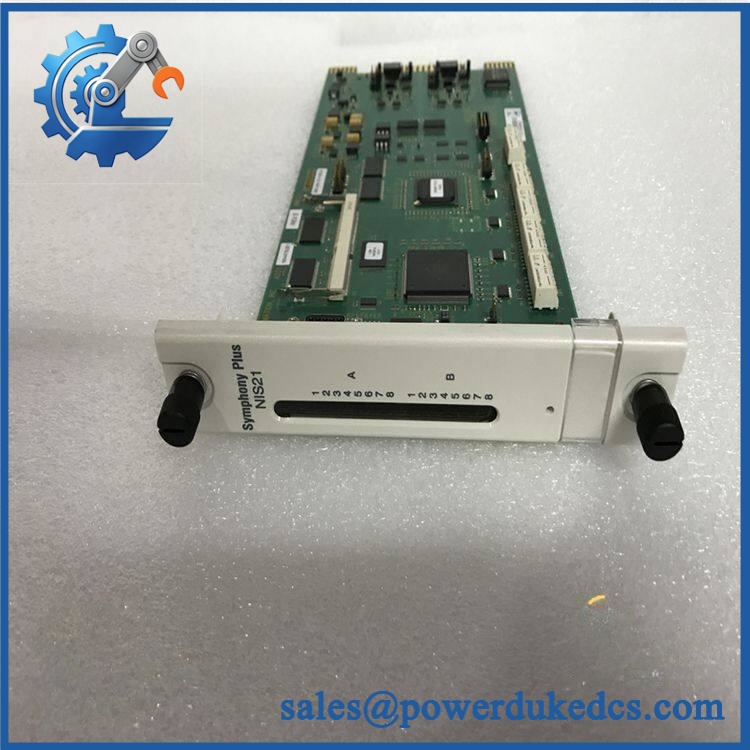
ABB SPCIS22
Module 4: Dynamic Emergency Swap & Configuration Guide
1. Pre-Swap Prep — isolate the signal group and map the termination hardware
Place the affected control section in its approved maintenance state. Record the SPCIS22 identification, mounting-unit position, termination-unit type, front-panel LED condition, and every connected signal group. Photograph the wiring before disconnecting anything. Confirm the supply architecture: +5 VDC, +15 VDC, -15 VDC, and +24 VDC are all part of the documented module power arrangement. Use ESD protection and a calibrated meter. The is designed around specific mounting and termination hardware, including IEMMU units and NFTP01/NTCS04-related interfaces.
2. Removal — release the module from its HR Series mounting arrangement
After the approved electrical isolation, disconnect the module from the applicable termination/interface assembly. Label connectors by channel group rather than by physical position alone. Release the from its mounting unit and withdraw it without bending the card or stressing the edge connectors. Inspect the mating contacts, termination unit, and adjacent wiring for corrosion, contamination, heat discoloration, or mechanical damage. A replacement card will not correct a failed termination interface.
3. Installation & Configuration — restore the exact I/O assignment
Insert the replacement into the original mounting position and secure it. Reconnect the termination/interface connections according to the cabinet drawing. Verify the configured channel functions: 4 × 4–20 mA analog inputs, 2 × 4–20 mA analog outputs, 3 digital inputs, and 4 digital outputs. Check any jumper-defined output defaults or channel settings against the original configuration. Do not substitute a faster SPQRS22 merely because it has similar functions; ABB specifically distinguishes the two devices by response performance and noise-rejection characteristics.
4. Power-On Self-Test (POST) — prove each signal path
Restore power and observe both available module-status indicators. The documented HR-series design includes front-panel status indication and a bus-fault protection function; the bus-fault timer disables digital outputs and forces analog outputs to their defined default values when controller clock activity is lost. Confirm normal module initialization, controller communication, analog input values, analog output response, digital input state changes, and digital output switching. Do not return automatic control until the affected process channels have been checked against calibrated simulation signals.
Module 5: Quality Assurance & Testing SOP
acceptance testing should cover all four signal classes and the module’s multiple supply rails.
- OEM Anti-Counterfeit Visual Inspection: Verify ABB markings, designation, PCB construction, connectors, mounting geometry, component placement, and revision markings.
- Serial and Identity Traceability: Photograph the complete module identification and record serial/revision information where available.
- Mechanical Inspection: Check the card edge, mounting points, connector contacts, housing, and termination interface.
- Power-Rail Verification: Test +5 VDC, +15 VDC, -15 VDC, and +24 VDC against the documented tolerance limits before functional testing.
- Power-On Self-Test (POST): Apply power and verify expected status LED behavior without persistent fault indication.
- Analog Input Full-Range Simulation: Inject calibrated 4–20 mA signals into all four analog-input channels and verify the reported process values at multiple test points.
- Analog Output Test: Command both 4–20 mA output channels through low, mid-scale, and high-scale values and measure the actual loop current with calibrated equipment.
- Digital Input Test: Exercise all three optically isolated inputs with the applicable field signal levels and verify state recognition.
- Digital Output Test: Command all four open-collector outputs and verify switching behavior into an appropriate controlled test load.
- Channel Isolation Check: Verify that stimulation of one channel does not create unintended activity on neighboring inputs or outputs.
- Bus Fault Simulation: Where the laboratory setup permits, simulate loss of controller bus timing and confirm the expected output-safe behavior.
- Termination Hardware Check: Verify compatibility and contact integrity of the installed mounting/termination assembly before final release.
- Temperature Observation: Operate the module through an extended powered test within its specified 0–70 °C ambient range where laboratory conditions permit.
- Final QC Record: Store channel measurements, power-rail results, identification photographs, test-equipment references, and technician sign-off.
ABB documents the as a programmable HR Series control I/O unit whose channels can be individually configured. Its digital outputs are optically isolated and open collector, while the analog I/O uses 4–20 mA signaling.
Module 6: Maintenance & Reliability FAQ
1. Is the a direct drop-in replacement, or does it require a firmware flash?
The is an I/O interface rather than the main process controller, so a conventional controller firmware upgrade is not normally the primary replacement issue. The important checks are the exact module type, mounting hardware, termination-unit compatibility, channel configuration, and controller-side I/O database. Verify those items against the installed system before replacement.
2. Is it safe to hot-swap this module while the system is running?
Do not assume live replacement is acceptable solely because the unit is an I/O plug-in assembly. Use the approved ABB/system maintenance procedure for the specific HR Series installation, especially because the module depends on multiple supply rails and interfaces directly with field I/O. The mounting and termination arrangement must remain electrically suitable throughout the intervention.
3. Will replacing this I/O module cause my current control program to be lost?
Replacing does not amount to replacing the main controller application. The greater risk is an incorrect I/O configuration after replacement. Back up the controller project, I/O database, signal assignments, scaling, alarm limits, and termination-unit documentation before removing the failed unit.
4. What should I test after installing the replacement?
Verify all supply rails first. Then test the four 4–20 mA inputs, two 4–20 mA outputs, three digital inputs, and four digital outputs according to the configured channel assignments. Check controller communication and confirm the process values match calibrated simulation equipment before returning the affected loops to automatic service.
5. What are the warranty terms if the unit fails post-installation?
Warranty coverage should be tied to the supplied serial number and documented stock condition. Hardware failure under specified operating conditions should be distinguished from faults caused by incorrect power rails, termination hardware, field wiring, overvoltage, ESD, or incorrect I/O configuration. The exact warranty duration and return procedure should be stated on the quotation before purchase.











 Start Chat


