

Description
- Brand: ABB
- Full Model Number: SPS01 / 2VAA008278R001
- Lifecycle Status: Current ABB MPS IV spare offering
- Core Function in System: 24 V DC power conversion for ABB MPS IV control-system loads
- Top 3 Hardcore Specs: +24 V DC output; 10 A output rating; MPS IV power-system architecture
- System Association: ABB MPS IV / Symphony Plus power system
- Mounting: Plug-in power system base
- Compatible Bases: BP01-L, BP01-M, BP01-R
- Redundancy: Designed for dual power-module arrangements within the MPS IV base system
- Condition & Lead Time: New OEM or tested replacement stock; emergency dispatch subject to confirmed physical inventory
ABB’s current documentation identifies 2VAA008278R001 as the SPS01 Power Supply, 24 V DC, 10 A for the MPS IV power system. ABB also documents BP01-L and BP01-R bases as supporting two SPS01 or SPS02 power modules.
Module 3: Technical Intro & Downtime Impact
A failed ABB SPS01 can remove a complete 24 V DC supply path from an MPS IV power system, potentially dropping downstream control and I/O loads even though the field process itself has not developed a mechanical fault. In a DCS cabinet, that distinction matters: loss of control power can create multiple secondary alarms at once and make the original failure harder to isolate. ABB identifies the SPS01 as a dedicated 24 V DC, 10 A power supply for MPS IV systems.
The electrical rating is the first replacement check. +24 V DC at 10 A is the documented output specification, and the SPS01 is installed as part of the MPS IV modular power architecture rather than as a generic DIN-rail supply. ABB’s MPS IV architecture uses dedicated BP01 bases for /SPS02 power modules, allowing multiple supply positions within the same power-system assembly. For MTTR control, verify the load budget and the companion base assembly before swapping the power module… replacing a 24 V source with an electrically similar but mechanically incompatible supply can create a second maintenance problem.
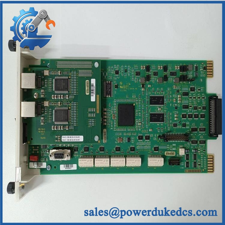
ABB SPS01 2VAA008278R001
Module 4: Dynamic Emergency Swap & Configuration Guide
1. Pre-Swap Prep — Confirm the Power-System Position
First identify / 2VAA008278R001, the MPS IV base position, and the associated cabinet load. Record which other supply module is installed beside it, as MPS IV bases are designed around defined SPS module combinations. ABB specifies the as 24 V DC, 10 A and documents bases for /SPS02 installation. Use LOTO, a calibrated multimeter, insulated tools, ESD protection, and the cabinet power-distribution drawing.
2. Removal — Isolate Cabinet Power Before Pulling the Supply
Do not rely on an indicator LED as proof that the module is de-energized. Isolate the cabinet power sources according to the approved maintenance procedure and verify the absence of the relevant DC voltage with a calibrated meter. Release the from its retaining hardware, disconnect it from the base interface, and remove the module without forcing the base connector. ABB’s MPS IV replacement procedure calls for the cabinet and field device to be powered down before removing installed power modules.
3. Installation & Configuration — Match Output and Base Compatibility
Insert the replacement / 2VAA008278R001 into the same MPS IV base position and secure it firmly. ABB specifically associates the with a +24 V DC, 10 A output and -series mounting bases. Reconnect the associated power-system wiring according to the cabinet drawing and verify polarity before energization. There are no PLC-style program parameters to transfer into the itself; compatibility is primarily electrical, mechanical, and architectural.
4. Power-On Self-Test (POST) — Verify DC Output Under Load
Restore cabinet power and verify that the MPS IV system starts without power-fail or supply-status alarms. Measure the output and confirm approximately 24 V DC under the approved operating condition. Then observe the downstream controller, I/O, and field-device power rails for stable operation. Where the system uses redundant supply arrangements, verify the required load-sharing or standby behavior with the companion supply rather than accepting a single-supply voltage check as the complete test.
Module 5: Quality Assurance & Testing SOP
The ABB / 2VAA008278R001 should receive a controlled power-supply acceptance test before entering critical-spares inventory.
- Identity verification: Record ABB designation, article number 2VAA008278R001, serial information, hardware revision, and visible product markings.
- OEM anti-counterfeit visual inspection: Check labels, enclosure markings, PCB identifiers, connectors, fasteners, and manufacturing details against established ABB references.
- Mechanical inspection: Examine the housing, mating connector, retaining hardware, cooling openings, and base interface for cracks, deformation, corrosion, or heat damage.
- Power-on self-test (POST): Energize the unit on an approved MPS IV test assembly and verify startup behavior and absence of supply-fault indications.
- Output-voltage verification: Measure the DC output against the documented +24 V DC nominal rating.
- Load test: Apply a controlled load within the specified operating limits and verify stable output regulation up to the required test current.
- 10 A capacity validation: Where the laboratory fixture permits, verify operation toward the documented 10 A output rating using a controlled electronic load.
- Protection-response test: Check the documented protection behavior using the approved ABB test procedure rather than applying uncontrolled short-circuit conditions.
- Base-interface inspection: Confirm proper mechanical seating and electrical contact with the appropriate base.
- Redundancy test: When the installation uses dual SPS modules, test the system’s response to removal or isolation of one supply under a controlled test condition.
- Thermal observation: Monitor the power module during sustained load operation for excessive temperature rise or abnormal behavior.
- Extended runtime test: Maintain the unit at representative load long enough to detect intermittent output instability or thermal drift.
- Final QC record: Retain serial-number photographs, voltage measurements, load-test results, thermal observations, test date, technician sign-off, and final pass/fail disposition.
ABB’s recent MPS IV documentation continues to list 2VAA008278R001 , 24 V DC, 10 A as part of the MPS IV power-system offering.
Module 6: Maintenance & Reliability FAQ
1. Is ABB a direct replacement, or does it require a firmware flash?
The is a power supply, not a programmable controller or CPU. A firmware transfer is therefore not part of a normal replacement. The critical checks are the exact ABB article number, 24 V DC / 10 A rating, compatible MPS IV base, cabinet wiring, and total load requirement.
2. Is it safe to hot-swap the while the system is running?
Do not assume it is safe merely because the MPS IV architecture can contain multiple supplies. ABB’s replacement procedure instructs technicians to turn off power to the cabinet and field device before removing installed power modules. Redundant supply arrangements can reduce process exposure, but live removal should only be performed when the exact system design and approved maintenance procedure explicitly permit it.
3. Will replacing cause my current control program to be lost?
Replacing the does not normally erase a controller application because the device is a power-supply component rather than application storage. The real risk is loss of control power to the equipment it feeds. Back up the controller configuration before planned maintenance anyway, and verify that the replacement supply does not overload the cabinet power budget.
4. What should I verify after installing ?
Verify the +24 V DC output, downstream DC distribution, supply alarms, controller startup, I/O status, and any redundant-supply behavior. ABB documents the as a 24 V DC, 10 A power supply within the MPS IV architecture, with bases supporting /SPS02 modules. A no-load voltage check is only the first acceptance step; test the supply under a representative load.
5. What are the warranty terms if the unit fails post-installation?
Warranty should follow the commercial terms for the specific unit and supplied condition. For a critical MPS IV spare, retain the serial number, pre-shipment test record, output-voltage measurements, load-test results, installation date, and cabinet alarm history. Those records help separate an failure from a defective base, overloaded DC bus, downstream short circuit, or cabinet wiring problem.











 Start Chat


