

Description
- Brand: ABB
- Full Model Number: SPS02
- ABB Article Number: 2VAA008279R001
- Product Family: MPS IV / Modular Power System IV
- Product Type: DC Power Supply Module
- Core Function in System: 48 VDC distribution for ABB MPS IV control-system power architecture
- Nominal Output: 48.0 VDC
- Output Capacity: 5 A
- Minimum Output: 47.5 VDC
- Maximum Output: 48.5 VDC
- Regulation: ±1% at full input and full load range
- Maximum Ripple / Noise: ≤150 mV peak-to-peak
- Holdup Time: 20 ms following power loss
- Load Sharing: Passive
- Compatible Base: BP01-L / BP01-M / BP01-R
- Base Capacity: Up to 2 SPS02 modules per applicable BP01 base
- Condition & Lead Time: Stock condition subject to inspection; emergency dispatch available subject to order confirmation
ABB’s current MPS IV documentation identifies SPS02, article number 2VAA008279R001, as a 48 VDC, 5 A power supply module. ABB also specifies that SPS02 is mounted on BP01 bases, with the documented BP01 family supporting two SPS02 units.
Module 3: Technical Intro & Downtime Impact
A failed DC power module can take an entire automation rack offline even when the controller, I/O cards, and communication equipment are individually healthy. With an MPS IV power system, loss of the 48 VDC rail can propagate into controller or field-interface faults, processor resets, communication interruptions, and repeated power-fail events. ABB SPS02, 2VAA008279R001, is the MPS IV power module specified for a 48.0 VDC output at 5 A, making it the appropriate power component when the existing system is designed around the voltage class. ABB’s current documentation explicitly lists as part of the MPS IV power architecture.
For MTTR, the useful numbers are clear. The output is specified from 47.5 to 48.5 VDC, with ±1% regulation at full input and load range and ≤150 mV peak-to-peak ripple/noise. ABB also specifies 20 ms holdup time after power loss and passive load sharing. A replacement must still be matched to the installed base and the system’s required output voltage; an SPS01 24 V module is not an electrical substitute for simply because both occupy the same base family.
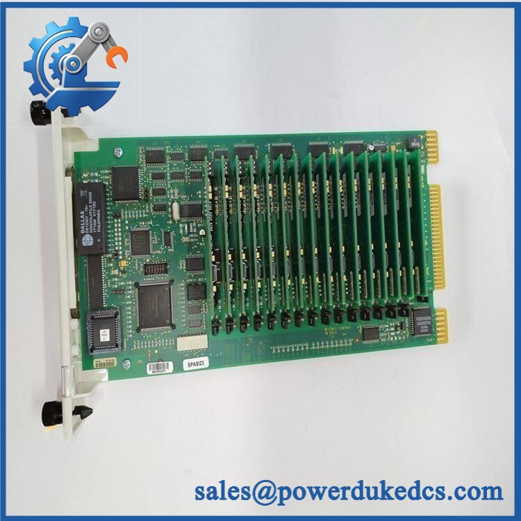
ABB SPS02 2VAA008279R001
Module 4: Dynamic Emergency Swap & Configuration Guide
1. Pre-Swap Prep — Isolate the DC Bus First
Put the MPS IV power system into the approved maintenance state and isolate the upstream AC/DC source according to the plant procedure. Verify that the DC bus has discharged before touching the power modules. Record the complete / 2VAA008279R001 identification, base type, module position, input wiring, redundancy arrangement, and downstream 48 VDC loads. Photograph the installed module and base before removal.
2. Removal — Release the From the Base
is a plug-in power module used with the base assembly, rather than a conventional DIN-rail supply. ABB documentation identifies -L, -M, and -R bases as supporting power modules; a assembly can accommodate two modules in the appropriate configuration. After confirming zero voltage, release the module’s mechanical retention and withdraw the vertically from the base interface. Do not loosen or disturb the base wiring unless the applicable replacement procedure requires it.
3. Installation & Configuration — Preserve the 48 VDC Architecture
Inspect the replacement before insertion and verify / 2VAA008279R001 on the label. Install it into the same position and ensure the module is fully seated. Where two modules are used for capacity or availability purposes, preserve the original module positions and base arrangement.
Check the output configuration before energization. ABB specifies 48.0 VDC nominal, with a 47.5–48.5 VDC operating output range and 5 A capacity. Do not substitute SPS01, SPS03, or SPS04 based solely on mechanical fit; ABB defines those modules for different output voltages and current requirements.
4. Power-On Self-Test (POST) — Verify Voltage Under Load
Restore the input supply and observe the MPS IV power-system status indications and any available power-fail monitoring. Measure the output before reconnecting the complete downstream load where the maintenance procedure permits. The target is approximately 48.0 VDC, within the documented output limits.
Then restore the downstream loads progressively and monitor output stability, ripple, abnormal heating, and any power-fail indications. If two modules are installed, verify the intended load-sharing behavior and confirm that the remaining supply architecture responds correctly to a simulated single-module loss. (A no-load voltage check alone can miss a supply that collapses once the real system load is applied.)
Module 5: Quality Assurance & Testing SOP
Each ABB / 2VAA008279R001 should undergo controlled power-supply testing before shipment.
- OEM anti-counterfeit visual inspection: Verify ABB markings, designation, article number, label quality, connector geometry, enclosure construction, and manufacturing workmanship.
- Exact part-number verification: Confirm 2VAA008279R001 against the physical label and inventory record. ABB’s current MPS IV documentation identifies this article number specifically as .
- Mechanical inspection: Check the housing, mounting interface, connectors, retaining features, cooling surfaces, corrosion, contamination, impact damage, and signs of unauthorized repair.
- Base compatibility test: Install the into an approved -L, -M, or -R test assembly and verify correct mechanical engagement.
- Power-on self-test (POST): Energize the module under controlled laboratory conditions and verify startup behavior and power-status indications.
- Output-voltage verification: Measure the nominal 48.0 VDC output and confirm operation within the documented 47.5–48.5 VDC range.
- Load test: Apply a controlled load through the module’s approved operating range and verify stable output up to the specified 5 A capacity.
- Regulation test: Verify output regulation against the documented ±1% specification at the applicable input and load conditions.
- Ripple/noise test: Measure output ripple/noise and verify it remains at or below the documented 150 mV peak-to-peak limit.
- Transient / holdup verification: Where the laboratory fixture supports it, verify the specified 20 ms holdup time following loss of input power.
- Load-sharing test: Where two modules are installed in the same assembly, verify passive current sharing and stable operation.
- Thermal observation: Monitor the module during extended loaded operation for abnormal heat rise, intermittent shutdown, fan or cooling problems where applicable, and connector heating.
- Power-fail monitoring: Confirm the relevant system fault/status indication responds correctly to an intentional input-power interruption where the test setup supports that check.
- Extended stability test: Run the module under representative load for an extended period and monitor voltage drift, ripple, resets, and abnormal temperature.
- Final QC record: Document article number, serial/asset identification, base tested, output voltage, load current, ripple, regulation, holdup results, test duration, photographs, technician sign-off, and packaging condition.
Module 6: Maintenance & Reliability FAQ
1. Is ABB a direct drop-in replacement, or does it require a firmware flash?
No firmware operation is normally associated with itself. It is a power-supply module within ABB’s MPS IV architecture. ABB identifies 2VAA008279R001 specifically as the 48 VDC / 5 A power module. The key replacement checks are the exact article number, base compatibility, correct input configuration, and downstream 48 VDC load.
2. Is it safe to hot-swap while the system is running?
Do not assume that live replacement is permitted merely because is a plug-in module. The MPS IV power system may be carrying the DC supply for active control hardware. Unless the exact cabinet and service documentation explicitly authorizes energized extraction, isolate the source, verify the bus is safe, and follow the plant’s electrical maintenance procedure.
3. Will replacing cause my current program or configuration to be lost?
is a power-supply module, not the controller or application-memory device. Replacing it therefore does not normally erase the controller program. The risk is operational: an uncontrolled power interruption can reset or stop downstream equipment. Before replacement, preserve the controller configuration and application backup, and verify that the MPS IV power system is fully restored before returning the control system to automatic service.
4. What should I verify before commissioning the replacement?
Verify / 2VAA008279R001, the base type, input supply arrangement, and required 48 VDC load. ABB specifies 48.0 VDC nominal, 5 A, with 47.5–48.5 VDC output, ±1% regulation, and ≤150 mV peak-to-peak ripple/noise. Measure the output both before and under representative load. Where redundant modules are installed, also verify load sharing.
5. What are the warranty terms if the unit fails after installation?
Warranty coverage should be stated on the quotation or sales order for the specific serialized unit. Retain the incoming inspection record, article-number photographs, base compatibility record, output-voltage readings, load-test results, ripple measurements, and commissioning report. For a DC power module, these records help distinguish an internal supply fault from an overloaded downstream circuit, defective base connection, or wiring problem.











 Start Chat


