

Description
- Brand: ABB
- Full Model Number: SYN5302A-Z,V217
- ABB Part Number: 3BHB006716R0217
- Series: SYNCHROTACT 5
- Lifecycle Status: Legacy generation; validate installed system revision before outage planning
- Core Function in System: Redundant automatic synchronization and synchrocheck for generator or line paralleling
- Top 3 Hardcore Specs: 24/48 VDC, 100–125 VAC/DC, or 220–250 VAC/DC auxiliary supply | 50–130 VAC U1/U2 measurement input | 25 W / 35 VA maximum consumption for SYN5302
- Channel Architecture: Two redundant SYN 5202 dual-channel systems; four channels total
- Parameter Capacity: Up to 7 parameter sets
- Mounting: Plug-in enclosure for 19-inch rack mounting
- Dimensions: 442 × 154 × 220 mm
- Weight: 8.0 kg
- Condition & Lead Time: Stock condition subject to inspection; emergency dispatch available subject to order confirmation and final QC
ABB documentation identifies SYN5302 as a redundant automatic dual-channel synchronization unit, with the device integrating two SYN 5202 systems for a four-channel arrangement.
Module 3: Technical Intro & Downtime Impact
A failed synchronization device can hold a generator breaker open, block an automatic paralleling sequence, or force operators into a slower manual synchronization procedure. In a power-generation environment, that delay can become a production constraint rather than a simple controls fault. ABB SYN5302A-Z,V217, part number 3BHB006716R0217, belongs to the SYNCHROTACT 5 family and is designed for redundant automatic synchronization and synchrocheck duties. ABB describes the SYN5302 architecture as two SYN 5202 dual-channel systems in one enclosure, normally providing four channels and allowing the alternate system to take over after a failure.
The engineering value is concentrated in fault tolerance and fast restoration. ABB specifies selectable auxiliary supplies of 24/48 VDC, 100–125 VAC/DC, or 220–250 VAC/DC, a 50–130 VAC measurement range for U1 and U2, and a maximum SYN5302 consumption of 25 W / 35 VA. The published measurement ranges include 10–100 Hz frequency and a -179° to +180° angle range, with synchronization timing represented from 0 to 1 second. Physical size is also significant: the SYN5302 enclosure is listed at 442 × 154 × 220 mm and 8.0 kg, with a 19-inch rack mounting arrangement.
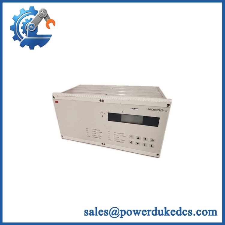
ABB SYN5302A-Z V217 3BHB006716R0217
Module 4: Dynamic Emergency Swap & Configuration Guide
1. Pre-Swap Prep — Isolate the Synchronization Circuit
Open and lock out the relevant auxiliary supply and verify absence of hazardous voltage before accessing the enclosure. Because the SYN5302 measures generator and system voltages and provides breaker-control contacts, do not treat it as a low-voltage plug-in I/O card. Record the existing 3BHB006716R0217 identification, hardware revision, terminal labels, communication connections, parameter-set assignments, and front-panel status indications. Have the approved wiring diagram, calibrated meter, insulated tools, and configuration backup available.
2. Removal — Release the Rack-Mounted Chassis
The ABB technical documentation identifies as a plug-in enclosure intended for 19-inch rack mounting. Disconnect and label field wiring before loosening the chassis retention hardware. Support the approximately 8.0 kg enclosure while withdrawing it from the rack; avoid pulling on terminal conductors, especially U1/U2 measurement wiring and breaker command circuits. Keep the removed unit available for side-by-side connector and revision comparison.
3. Installation & Configuration — Restore the Existing Protection Logic
Slide the replacement into the same rack position and secure the mechanical fasteners before reconnecting wiring. Match every terminal against the approved site drawing rather than relying on wire color. Confirm the auxiliary supply range first; ABB documents multiple supply variants, so the plant wiring must correspond to the ordered configuration. Restore the same parameter-set selection and synchronization limits, including voltage, frequency, slip, acceleration, breaker closing time, and any communication settings. The SYNCHROTACT 5 platform supports up to seven parameter sets and provides SynView-based parameter management.
4. Power-On Self-Test (POST) — Verify Both Synchronization Channels
Apply auxiliary power under controlled conditions and inspect the front-panel READY, OPERATING, BLOCKED, and ERROR indications for each side. Then confirm that U1 and U2 measurements are present and plausible, frequency values are stable, and the measured phase relationship responds correctly to the test condition. The critical acceptance point is not simply a healthy display; the synchronizer must correctly recognize permissible synchronization conditions before the breaker command circuit is released. (A mismatched parameter set can produce an apparently healthy start-up while still preventing a valid close command.)
Module 5: Quality Assurance & Testing SOP
Every ABB SYN5302A-Z,V217 / 3BHB006716R0217 unit should undergo controlled inspection before shipment. The test record should stay with the serialized asset.
- OEM anti-counterfeit visual inspection: Verify ABB markings, identification labels, board and chassis construction, connector geometry, revision markings, and physical consistency with known SYNCHROTACT 5 hardware.
- Part-number verification: Confirm SYN5302A-Z,V217 and 3BHB006716R0217 before any electrical test.
- Mechanical inspection: Check the 19-inch mounting frame, fasteners, terminal interfaces, front-panel indicators, enclosure condition, and signs of corrosion or unauthorized repair.
- Power-input verification: Test only against the supply configuration documented for the specific unit; ABB publishes several auxiliary-voltage variants for the SYNCHROTACT 5 family.
- Power-on self-test (POST): Energize the unit under controlled bench conditions and check READY / OPERATING / BLOCKED / ERROR indications on both synchronization sections.
- Measurement simulation: Inject approved test voltages for U1 and U2 within the documented 50–130 VAC measurement range and verify corresponding displayed values.
- Frequency simulation: Verify response across the applicable frequency range, with ABB documentation specifying a measurement range of 10–100 Hz.
- Phase-angle verification: Test the synchronization angle response against the published -179° to +180° range.
- I/O full-range simulation: Exercise applicable digital inputs, breaker command outputs, adjustment commands, and signaling contacts through the approved test fixture.
- Communication check: Where fitted, verify the configured communications interface and SynView service connection according to the ordered communication option. ABB documentation identifies interfaces including Modbus, Profibus, LON, and IEC 61850 across the SYNCHROTACT 5 family.
- Redundancy test: Confirm independent operation of the two internal SYN 5202 systems and verify that the intended alternate synchronization path remains available after simulated primary-channel failure.
- Final QC release: Record serial data, revision information, measured values, alarm results, photographs, technician sign-off, and packaging status.
Module 6: Maintenance & Reliability FAQ
1. Is ABB SYN5302A-Z,V217 a direct drop-in replacement, or does it require a firmware flash?
Do not assume a firmware flash is required. The more important issue is exact hardware and configuration compatibility: SYN5302A-Z,V217, 3BHB006716R0217, supply variant, communication option, and site parameter set should all be matched. ABB documents SynView as the configuration and maintenance tool for SYNCHROTACT 5 and supports parameter management through the device interface.
2. Is it safe to hot-swap this unit while the system is running?
No. The is a rack-mounted synchronization device connected to generator/system voltage measurements and breaker-control circuits. ABB documentation does not present it as a hot-swappable device. Isolate the auxiliary supply and all relevant field energy sources before removal, then follow the plant switching and synchronization safety procedure.
3. Will replacing ,V217 cause my current synchronization parameters to be lost?
The replacement device itself will not automatically preserve the configuration stored in the removed unit. Before shutdown, export or document the active SynView parameter configuration, all seven parameter-set assignments where applicable, communication settings, and synchronization limits. ABB states that SYNCHROTACT 5 can store up to seven parameter sets and that SynView supports parameter setting and actual-value monitoring. Retain a readable backup outside the equipment enclosure.
4. How do I verify that the replacement is actually synchronizing correctly?
Start with U1/U2 voltage presence and frequency agreement, then verify phase-angle behavior and the synchrocheck decision. The documented SYNCHROTACT 5 measurement ranges include 0–1.3 × Un for U1/U2, 10–100 Hz frequency, and -179° to +180° angle measurement. Do not prove the replacement solely by confirming that the front display powers up; perform a controlled synchronization test before authorizing a breaker close.
5. What are the warranty terms if the unit fails after installation?
Warranty coverage should be stated on the quotation and sales order for the specific serialized unit. For commissioning records, retain the incoming inspection report, part-number photographs, installation date, auxiliary-voltage measurement, parameter backup, event history, and post-installation test results. That evidence provides the clearest basis for determining whether a failure is attributable to the supplied unit or to the surrounding synchronization circuit.











 Start Chat


