

Description
- Brand: ABB
- Full Model Number: SYN5302A-Z,V277
- ABB Part Number: 3BHB006716R0277
- Product Family: SYNCHROTACT 5
- Product Type: Redundant automatic dual-channel synchronizing device
- Core Function in System: Automatic generator/grid synchronization and synchrocheck for power-circuit-breaker closing
- Architecture: 2 × independent SYN 5202 dual-channel systems
- Total Synchronizing Channels: 4
- Communication Option: IEC 61850
- IEC 61850 Interface: Ethernet RJ45
- Parameter Sets: 7
- Auxiliary Supply: 100–230 VAC or 24–250 VDC nominal
- Permissible Supply: 75–300 VAC or 18–300 VDC
- Measuring Input U1/U2: 50–130 VAC nominal
- Frequency Range: 10–100 Hz
- Digital Inputs: 24/48 VDC, 6–8 mA
- Paralleling Relay Rating: 250 VAC/VDC, 10 A continuous
- Maximum Power Consumption: 25 W / 35 VA
- Mounting: Semi-flush or surface mounting; SYN 5302 panel cutout 443 × 155 mm
- Weight: 8 kg
- Operating Temperature: +5 to +55°C with communication
- Condition & Lead Time: Stock condition subject to inspection; emergency dispatch available subject to order confirmation
ABB’s ordering table maps SYN 5302 – 5277 to a redundant automatic dual-channel synchronizing device with IEC 61850 communication, 50/60 Hz nominal frequency, and seven parameter sets. The supplied designation SYN5302A-Z,V277 / 3BHB006716R0277 corresponds to this V277 configuration.
Module 3: Technical Intro & Downtime Impact
A synchronizer failure can keep a healthy generator from being paralleled because the breaker-close permissive depends on verified voltage, frequency, slip, and phase-angle conditions. ABB SYN 5302 is specifically built for this protection-critical task. It contains two SYN 5202 dual-channel systems in one enclosure, giving four channels; normally, the output contacts are wired in series, while one complete dual-channel system can be bypassed when necessary. That architecture is intended to maintain both security against incorrect closing and availability after a single-system failure.
For MTTR, the V277 configuration has several useful fixed references. ABB specifies 100–230 VAC or 24–250 VDC nominal auxiliary power, 50–130 VAC U1/U2 measurement inputs, 10–100 Hz frequency measurement, and 25 W / 35 VA maximum consumption for SYN 5302. The unit also provides seven parameter sets, while the V277 ordering code specifically corresponds to IEC 61850 communication. With the communication option installed, ABB specifies an RJ45 Ethernet interface for IEC 61850.
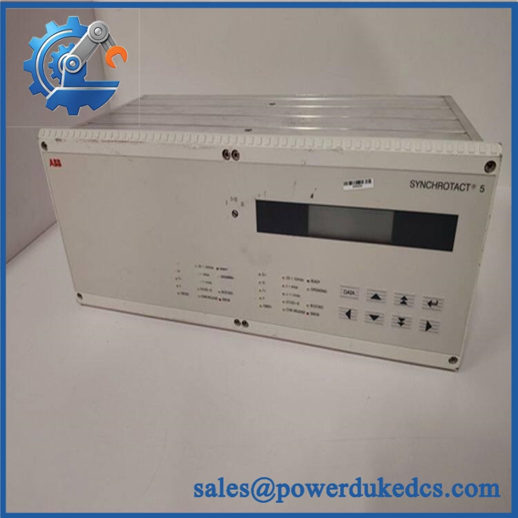
ABB SYN5302A-Z V277 3BHB006716R0277
Module 4: Dynamic Emergency Swap & Configuration Guide
1. Pre-Swap Prep — Capture the Synchronizing Logic Before Isolation
Place the generator or bus-paralleling scheme into the plant’s approved maintenance state. Record the complete SYN5302A-Z,V277 / 3BHB006716R0277 identification, system-selection status, active parameter set, breaker assignment, U1/U2 wiring, digital-input assignments, output-contact wiring, and IEC 61850 network settings. Save the existing parameter file through SynView where available; ABB states that SynView stores parameter files and supports comparison between the device and PC configuration.
2. Removal — Treat the Device as a Panel-Mounted Synchronizer
SYN 5302 is a panel-mounted device rather than a DIN-rail card. ABB’s dimensional documentation specifies a 443 × 155 mm panel cutout for SYN 5302, and the unit weighs approximately 8 kg. Isolate the auxiliary supply and relevant measurement/control circuits according to the switching procedure, label every terminal and communication connection, release the panel-retention hardware, and support the enclosure while extracting it.
Do not disturb VT wiring or breaker-control wiring unnecessarily. The U1/U2 measurement inputs are part of the synchronization decision, while the output contacts form part of the breaker-close permissive chain.
3. Installation & Configuration — Reproduce , Not Just SYN 5302
Verify SYN5302A-Z,V277 and 3BHB006716R0277 before installation. ABB’s ordering system distinguishes the configuration by its communication, auxiliary-frequency, and parameter-set options; specifically, 5277 denotes IEC 61850, 50/60 Hz, and seven parameter sets for SYN 5302.
Reconnect U1/U2, digital I/O, breaker-control contacts, and the Ethernet communication interface exactly as documented. Restore the seven parameter sets and verify the selected paralleling point. Where IEC 61850 is used, confirm the Ethernet configuration and the associated signals; ABB specifies that IEC 61850 transmits digital I/O, status information, and measured values through the RJ45 interface.
4. Power-On Self-Test (POST) — Prove the Breaker-Closing Decision
Apply auxiliary power under controlled conditions and verify normal startup without an internal-fault indication. Confirm the selected parameter set and check the actual U1/U2 values, frequency, voltage difference, slip, and phase angle.
Then perform a controlled synchronizing test. ABB’s parameter ranges include a 1–99° angle window, 0–6% slip limit for channel 1, and 0–40% maximum voltage difference for channel 1; channel-2 settings have their own ranges. Paralleling-time and breaker-command parameters are also configurable. Finally, verify the breaker command path and IEC 61850 status exchange before returning the generator to automatic service.
Module 5: Quality Assurance & Testing SOP
Each ABB SYN5302A-Z, / 3BHB006716R0277 should receive a complete synchronizing-system test before shipment.
- OEM anti-counterfeit visual inspection: Verify ABB markings, SYN 5302 designation, configuration, 3BHB006716R0277 identification, enclosure construction, front panel, connectors, and board workmanship.
- Exact type verification: Confirm the complete SYN 5302 – 5277 configuration against the physical nameplate and purchasing record. ABB identifies this code as IEC 61850, 50/60 Hz, seven-parameter-set configuration.
- Mechanical inspection: Check panel hardware, connectors, terminal blocks, front controls, labels, enclosure, and signs of corrosion, impact, contamination, or unauthorized repair.
- Auxiliary-power test: Verify operation across the applicable documented supply configuration: 100–230 VAC or 24–250 VDC nominal.
- Power-on self-test (POST): Energize the unit and verify startup diagnostics, status indicators, system selection, and internal-fault supervision.
- Voltage-input test: Apply calibrated U1/U2 test signals within the 50–130 VAC nominal measurement range and verify actual-value indication.
- Frequency simulation: Exercise the synchronizer across the applicable 10–100 Hz measurement range.
- Phase-angle simulation: Sweep controlled phase relationships and verify the configured angle-window behavior.
- Slip simulation: Apply positive and negative frequency differences and confirm correct slip-limit detection.
- Voltage-difference test: Simulate controlled U1/U2 magnitude differences and confirm the synchronization permissive follows the configured threshold.
- Breaker-command test: Verify paralleling-command generation, command duration, lead-angle behavior, and configured monitoring time without connecting an uncontrolled production breaker.
- Digital I/O full-range simulation: Exercise the seven-parameter-set selection inputs, test-mode input, start/stop/blocking functions, reset input, and configured signaling outputs. ABB documents seven additional digital inputs and seven relay outputs for devices with seven parameter sets.
- Redundancy test: Simulate failure of one internal dual-channel system and verify that the alternate system can be selected as designed. ABB specifically documents the SYN 5302 dual-system architecture and system selector function.
- IEC 61850 test: Verify Ethernet connectivity, configured IED communication, digital-status transmission, and measured-value exchange through the RJ45 interface.
- Relay-contact test: Verify the paralleling contacts against the published 250 VAC/VDC and 10 A continuous maximum rating without exceeding the approved laboratory limits.
- Event/configuration verification: Confirm parameter-set assignment and verify that the stored event information and configuration are readable through the service interface.
- Extended stability test: Run repeated synchronization simulations while monitoring for resets, parameter corruption, intermittent communications, or unexplained release/block conditions.
- Final QC record: Record part number, full type code, firmware/configuration information, supply voltage, U1/U2 test values, frequency, angle, slip, voltage-difference results, I/O results, IEC 61850 test, redundancy test, photographs, technician sign-off, and packaging condition.
Module 6: Maintenance & Reliability FAQ
1. Is ABB SYN5302A-Z, a direct drop-in replacement, or does it require a firmware flash?
The exact configuration is important. ABB’s ordering data identifies SYN 5302 – 5277 as the redundant automatic dual-channel version with IEC 61850, 50/60 Hz, and seven parameter sets. A firmware flash should not be assumed merely because the device is replaced. The required task is to restore the validated parameter sets and verify the communication configuration and exact system architecture.
2. Is it safe to hot-swap this synchronizer while the generator is running?
No. SYN 5302 is connected to VT measurement circuits, digital control signals, and breaker-command contacts. Use the plant’s approved generator-paralleling isolation procedure and establish the required protection/control bypass before removal. The unit should not be treated as a live-replaceable I/O card.
3. Will replacing , cause my current synchronizing settings to be lost?
The replacement unit must be treated as requiring configuration restoration. ABB states that SYNCHROTACT 5 devices can store seven parameter sets, allowing different settings for up to seven paralleling points. SynView can store the parameter files on a PC and compare device settings with the saved file. Back up the active parameter sets, breaker assignment, synchronization limits, command timing, and communication configuration before removal.
4. What should I verify before commissioning the replacement?
Verify the complete , / 3BHB006716R0277 identity first. Then check the 100–230 VAC or 24–250 VDC nominal auxiliary supply, 50–130 VAC U1/U2 input, 10–100 Hz frequency range, active parameter set, breaker-close timing, and IEC 61850 configuration. Finally, prove the synchronization decision with controlled voltage, frequency, slip, angle, and breaker-command tests.
5. What are the warranty terms if the unit fails after installation?
Warranty coverage should be stated on the quotation or sales order for the specific serialized unit. Retain the incoming inspection record, complete type-code photographs, parameter backup, IEC 61850 configuration, secondary-injection results, breaker-command test, and commissioning report. For a synchronizer, those records are particularly useful when distinguishing a device failure from VT wiring, incorrect synchronization limits, breaker closing-time changes, or network-communication problems.











 Start Chat


