

Description
- Brand: ABB
- Full Model Number: TU836V1 / 3BSE013237R1
- Lifecycle Status: Legacy AC 800M I/O accessory; verify current stock and compatibility
- Core Function in System: Compact Module Termination Unit for ABB S800 I/O
- Top 3 Hardcore Specs: S800 I/O interface; 24 V DC field-power distribution; 16-channel termination architecture
- System Association: ABB S800 I/O / AC 800M
- Form Factor: DIN-rail-mounted termination unit
- Connection: I/O module interface plus field-terminal connections
- Condition & Lead Time: New OEM or tested replacement stock; emergency dispatch subject to confirmed inventory
The TU836V1 / 3BSE013237R1 belongs to ABB’s S800 I/O termination-unit family. The TU836 series is used to terminate field wiring and interface it with S800 I/O modules, making the unit a wiring and signal-distribution component rather than a processor.
Module 3: Technical Intro & Downtime Impact
A damaged termination unit can create a deceptively difficult I/O fault. The controller may remain healthy while several field channels show intermittent, missing, or incorrect status because the problem sits at the physical interface between the field wiring and the S800 I/O electronics. The ABB TU836V1 provides the field-termination and interface function required by compatible I/O configurations, so a failed or incorrectly wired unit can increase troubleshooting time across multiple channels.
For MTTR, the key is preserving the original channel and terminal mapping. The TU836V1 is a physical termination assembly, not a programmable CPU, so there is normally no application firmware to transfer into the unit itself. During replacement, verify the exact I/O module type, field-voltage arrangement, terminal assignment, and installed base configuration. (For older AC 800M cabinets, inspect screw terminals and conductor ferrules at the same time; a loose termination can produce the same symptom as a failed TU836V1.)
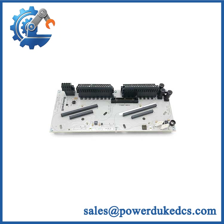
ABB TU836V1 3BSE013237R1
Module 4: Dynamic Emergency Swap & Configuration Guide
1. Pre-Swap Prep — Freeze the Existing I/O Map
Put the affected I/O group into its approved maintenance state and document the complete terminal assignment before disconnecting anything. Photograph every wire, terminal number, cable shield, and I/O module position. Confirm that the replacement is TU836V1 / 3BSE013237R1 and check the associated I/O module against the cabinet drawing. Use ESD protection, insulated tools, a calibrated multimeter, and the applicable ABB wiring diagram.
2. Removal — Release the Termination Unit From the DIN Rail
After applying the site’s electrical isolation procedure, disconnect the field wiring one circuit at a time and keep the original terminal labels intact. Release the termination unit from its DIN-rail mounting mechanism and separate it from the associated I/O interface without forcing the mating connector. Do not pull multiple conductors simultaneously; preserving channel identity is essential when several signals share the same termination assembly.
3. Installation & Configuration — Match Every Field Terminal
Mount the replacement in the original position and reconnect the I/O interface. Transfer each field conductor to the corresponding terminal using the documented wiring diagram, including any supply, return, and shield connections. There is no CPU-style program or node address to download into the itself; configuration compatibility comes from the associated I/O hardware and the AC 800M application.
4. Power-On Self-Test (POST) — Verify Channel Integrity
Restore power under the approved commissioning procedure and confirm that the associated I/O module starts without diagnostic faults. Check each required input or output channel individually from the controller engineering system, then compare the software state with the actual field signal. For analog circuits, verify representative low, midpoint, and high values; for digital circuits, exercise both ON and OFF states. A healthy I/O module with one incorrectly landed wire is still a failed maintenance job.
Module 5: Quality Assurance & Testing SOP
The / 3BSE013237R1 should be tested as an I/O termination interface, with emphasis on mechanical integrity and channel continuity.
- Identity verification: Record ABB designation, , article number 3BSE013237R1, revision markings, and serial information where available.
- OEM anti-counterfeit visual inspection: Examine labels, molded markings, terminal construction, connectors, retaining hardware, and manufacturing identifiers.
- Mechanical inspection: Check the DIN-rail latch, enclosure, mating interface, terminal screws, terminal separators, and mounting points for cracks or deformation.
- Terminal inspection: Verify every field terminal for secure clamping, correct hardware, corrosion, contamination, and damaged conductor entry points.
- Continuity testing: Verify the expected electrical path between each applicable field terminal and its corresponding I/O interface connection using a controlled low-voltage test.
- Power-on self-test (POST): Install the unit with a compatible I/O module and verify normal startup and absence of interface-related diagnostic faults.
- I/O full-range simulation: Exercise the connected I/O channels through their applicable electrical range and confirm correct controller indication.
- Digital channel testing: Simulate both logical states on required digital channels and confirm correct input or output response.
- Analog channel testing: Where applicable, inject calibrated representative signals and confirm stable readings at the AC 800M controller.
- Shield/ground verification: Check shield and reference connections against the specific cabinet drawing rather than assuming a universal terminal arrangement.
- Thermal and intermittent check: Operate the assembly under representative load and inspect for intermittent signal loss, abnormal heating, or unstable contact.
- Final QC record: Retain photographs, continuity measurements, I/O test results, terminal mapping, test date, technician sign-off, and final pass/fail status.
Module 6: Maintenance & Reliability FAQ
1. Is ABB a direct drop-in replacement, or does it require a firmware flash?
The is a termination/interface component, not an application CPU. A firmware flash is therefore not normally part of its replacement. The critical check is compatibility with the installed I/O module and the exact field-wiring arrangement. Verify 3BSE013237R1 and the cabinet documentation before installation.
2. Is it safe to hot-swap the while the system is running?
Do not assume that it is hot-swappable. Even if the wider I/O architecture supports certain live-maintenance functions, the specific termination unit, field circuits, and installation determine whether live replacement is permitted. For emergency maintenance, follow the approved isolation procedure unless the exact ABB configuration explicitly authorizes live work.
3. Will replacing cause my current AC 800M program to be lost?
No application program is normally stored in the termination unit itself. The AC 800M controller and associated I/O configuration remain separate. Still, record the existing I/O channel assignments and configuration before replacement; the greater practical risk is reconnecting a field conductor to the wrong terminal.
4. What should I verify after installing ?
Verify mechanical seating, every field-wire termination, supply/reference wiring, associated I/O diagnostics, and the complete channel map. Then test each affected field signal from end device to controller. For an analog loop, use calibrated signal injection; for a digital circuit, prove both states.
5. What are the warranty terms if the unit fails post-installation?
Warranty should follow the commercial terms for the exact unit and supplied condition. Keep the serial or identification record, incoming inspection photographs, continuity results, I/O test report, installation date, and any diagnostic logs. These records help distinguish a defective termination unit from loose wiring, a failed I/O module, or a field-device fault.











 Start Chat


