

Description
- Brand: ABB
- Full Model Number: TY805
- Part Number: 3BSE080253R1
- Product Family: S800 I/O
- Product Type: Shunt Stick
- Core Function in System: Signal shunting and transmitter-power current limitation for compatible analog input termination units
- Resistance: 125 + 125 Ω
- Current Limitation: Built-in
- Compatible I/O: AI845 / AI880A
- Compatible MTUs: TU834 / TU844 / TU845 / TU854
- Form Factor: Small plug-in/passive accessory for S800 I/O termination-unit circuitry
- Operating Temperature: 0 to +55°C
- Storage Temperature: -25 to +70°C
- Protection Class: IP20
- Condition & Lead Time: Stock condition subject to inspection; emergency dispatch available subject to order confirmation
ABB’s official S800 I/O documentation describes TY805 as a 125 + 125 Ω shunt stick with current limitation, intended for AI845 and AI880A analog-input modules when used with TU834, TU844, TU845, or TU854 termination units. ABB currently packages eight TY805 pieces under TY805K01, article 3BSE081160R1.
Important part-number note: the exact 3BSE080253R1 supplied in your list is reported by secondary inventory sources as TY805, while ABB’s current official product selector identifies the packaged eight-piece TY805K01 as 3BSE081160R1. Verify the physical label and packaging quantity before purchasing or listing the item.
Module 3: Technical Intro & Downtime Impact
A missing or failed shunt device can create a deceptively simple analog-input problem: the AI channel may stop reading correctly, a transmitter circuit may lose its intended conditioning, or the expected current-limiting behavior may no longer be present. ABB TY805 is a passive S800 I/O accessory designed specifically around these termination-unit circuits. ABB describes it as a 125 + 125 Ω shunt with built-in current limitation for AI845 and AI880A used with the specified TU834, TU844, TU845, and TU854 termination units.
For MTTR, the critical issue is compatibility rather than software configuration. TY805 is not a CPU, communication card, or programmable I/O module; it is a small passive component whose resistance and current-limiting characteristics form part of the signal interface. ABB’s documentation identifies the 125 + 125 Ω value and its intended AI/MTU combinations. The official hardware selector also specifies 0 to +55°C operating temperature, -25 to +70°C storage, IP20, and S800 I/O mechanical classification for the current package.
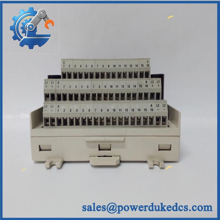
ABB TY805 3BSE080253R1
Module 4: Dynamic Emergency Swap & Configuration Guide
1. Pre-Swap Prep — Identify the Exact AI and MTU Combination
Place the affected I/O channel into the plant’s approved maintenance state and isolate the relevant field circuit where required. Confirm that the channel uses AI845 or AI880A and that the termination unit is one of TU834, TU844, TU845, or TU854. Record the installed identification, photograph its exact position, and note whether the existing component is part of a current transmitter circuit or another configured signal path.
2. Removal — Remove the Shunt Without Disturbing the MTU
is a small accessory associated with the S800 I/O termination-unit interface rather than a rack CPU or conventional plug-in I/O card. ABB identifies its use directly with the supported AI and MTU combinations. After the circuit is made safe, release the shunt from its designated termination-unit position using the approved extraction method. Do not lever against adjacent terminals or bend the MTU contacts; a damaged socket can create a second fault after the original problem is corrected.
3. Installation & Configuration — Verify Resistance and Application
Before installation, confirm and the applicable part identification against the removed item. Insert the replacement into the same termination-unit location and verify that it is fully seated.
There is normally no firmware or parameter download associated with the shunt itself. The critical configuration is physical: the correct 125 + 125 Ω shunt, installed on the supported AI845/AI880A + TU834/TU844/TU845/TU854 combination. ABB specifically identifies these compatibility relationships. Do not substitute a TY801 or TY804 merely because it fits the same general I/O accessory location; their electrical functions differ.
4. Power-On Self-Test (POST) — Prove the Analog Channel
Restore the field circuit according to the plant procedure and inspect the AI diagnostic status. Check that the transmitter or simulated source receives the expected interface conditions and that the AI channel reports a stable value without open-circuit, over-range, or wiring diagnostics.
Then perform a controlled signal simulation across the configured operating range. Compare the measured AI value against the expected transmitter response. A correct result should include stable readings and no unexpected current-limiting behavior beyond the design of the circuit.
Module 5: Quality Assurance & Testing SOP
Each ABB / 3BSE080253R1 should receive component-level and application-specific inspection before shipment.
- OEM anti-counterfeit visual inspection: Check ABB identification, marking, physical construction, contact geometry, finish, and consistency with known I/O accessories.
- Part-number verification: Confirm the supplied / 3BSE080253R1 against the physical label and purchasing record. Note that ABB’s current official eight-piece package is TY805K01 / 3BSE081160R1.
- Mechanical inspection: Check contacts, body condition, cracks, contamination, corrosion, deformation, and evidence of previous modification.
- Resistance verification: Measure the two specified 125 Ω resistance sections independently with a calibrated meter and compare against the approved tolerance.
- Current-limitation verification: Use an approved low-energy test fixture to verify the intended current-limiting behavior without exceeding component or laboratory safety limits.
- MTU compatibility test: Install the into a compatible TU834/TU844/TU845/TU854 test assembly and verify physical engagement.
- AI interface test: Connect an approved AI845 or AI880A test setup and verify stable signal behavior.
- I/O full-range simulation: Exercise the supported analog-input channel across its approved test range and verify repeatable engineering-unit conversion.
- Fault simulation: Where supported by the test fixture, simulate open/abnormal transmitter conditions and confirm the AI system produces the expected diagnostic response.
- Thermal observation: Monitor the shunt and adjacent termination-unit contacts during representative operation for abnormal heating.
- Extended stability test: Maintain representative signal conditions and verify there is no intermittent contact or drift.
- Final QC record: Document part identification, resistance measurements, host AI module, MTU type, signal-test results, inspection photographs, technician sign-off, and packaging condition.
Module 6: Maintenance & Reliability FAQ
1. Is ABB a direct drop-in replacement, or does it require a firmware flash?
is a passive shunt accessory, so there is no normal firmware-flashing procedure. The important requirement is matching the electrical function and host hardware. ABB specifies as a 125 + 125 Ω shunt with current limitation for and with , , , or termination units.
2. Is it safe to hot-swap while the system is running?
Do not assume that it is safe to remove the shunt from an energized termination unit. The associated transmitter circuit may remain powered, and removing the component can disturb the analog signal. Follow the plant’s I/O maintenance procedure and isolate the relevant channel before physical removal unless the exact ABB installation documentation explicitly authorizes energized replacement.
3. Will replacing cause my current program or configuration to be lost?
No firmware or application program resides in the shunt. Replacing it does not normally alter the controller program or AI configuration. The risk is instead a temporary loss or disturbance of the affected field signal. Record the original channel status and configured engineering value before replacement so the post-repair reading can be compared directly.
4. What should I verify before commissioning the replacement?
Verify the complete signal path: → compatible MTU → / → controller configuration. Confirm the required 125 + 125 Ω shunt arrangement and current-limiting function. ABB explicitly lists the supported AI and MTU combinations. Also verify the exact part-number discrepancy before procurement: ABB’s current eight-piece package is TY805K01 / 3BSE081160R1, while 3BSE080253R1 appears in secondary inventory records as individual stock.
5. What are the warranty terms if the unit fails after installation?
Warranty coverage should be stated on the quotation or sales order for the supplied item. Keep the incoming inspection record, resistance measurements, package/quantity photographs, host AI/MTU identification, and post-installation signal test results. For a passive shunt, those records are especially useful because a bad termination contact, transmitter fault, or incorrect MTU combination can produce symptoms similar to a defective .











 Start Chat


