

Description
- Brand: ABB
- Full Model Number: UAA326A04
- ABB Part Number: HIEE300024R4
- Additional Identification: HI903818-310
- Lifecycle Status: Legacy industrial spare; current OEM availability requires verification
- Core Function in System: Industrial I/O interface board for legacy ABB control equipment
- Top 3 Hardcore Specs: UAA326A04 identification; HIEE300024R4 part number; HI903818-310 board designation
- Board Format: Rack-mounted printed circuit board with front extraction hardware
- Reported Series: Legacy ABB I/O/control hardware
- Power Requirement: Application-specific; public records are inconsistent
- Condition & Lead Time: New, refurbished, or repaired inventory subject to physical inspection; emergency dispatch based on confirmed stock
Available records consistently associate UAA326A04, HIEE300024R4, and HI903818-310 with the same ABB board, and one dedicated industrial-parts record explicitly describes it as an I/O module. Public listings also show the unit as a card-style board with a front panel and rack-extraction hardware.
Module 3: Technical Intro & Downtime Impact
When a legacy ABB control rack loses an I/O board, the failure can appear as missing field signals, unavailable interlocks, or a control sequence that suddenly stops responding. ABB UAA326A04, HIEE300024R4 is identified in available component records as an I/O board associated with HI903818-310. Its card-style construction is intended for rack installation, so exact board identification and connector compatibility become the first checks during an emergency replacement.
For MTTR reduction, the strongest verified identifiers are the complete UAA326A04 / HIEE300024R4 / HI903818-310 combination and the physical card construction. Public sources do not provide a consistent, authoritative set of channel counts, signal ranges, supply voltage, or communications specifications for this exact board. Several secondary listings assign conflicting product functions and electrical ratings. —That is a reason to use the installed board’s nameplate, rack drawing, terminal schedule, and original system documentation as the commissioning authority rather than copying generic online specifications.
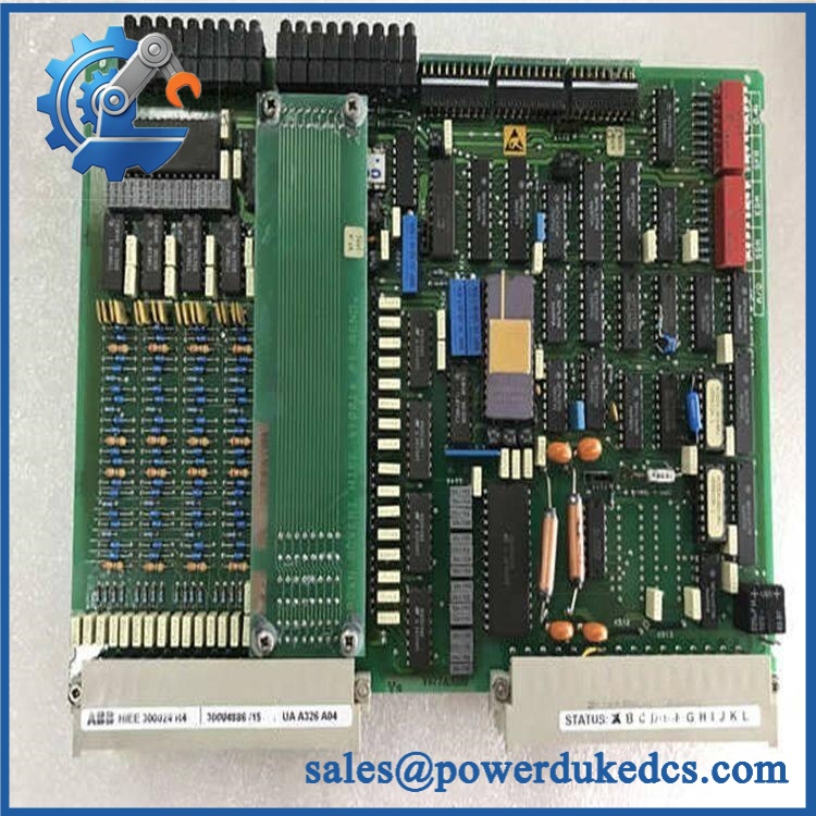
ABB UAA326A04 HIEE300024R4
Module 4: Dynamic Emergency Swap & Configuration Guide
1. Pre-Swap Prep — Freeze the original I/O configuration
- Place the affected ABB control system in the approved maintenance state.
- Isolate the associated control power according to the cabinet procedure.
- Verify absence of hazardous voltage before removing the card.
- Record UAA326A04 / HIEE300024R4 / HI903818-310 exactly as marked.
- Photograph the front panel, rear connector area, rack position, and adjacent cards.
- Record the exact slot position and neighboring board arrangement.
- Document every connected field circuit and terminal assignment.
- Save the existing control-system configuration before disturbing the rack.
- Use ESD protection and an antistatic work surface.
2. Removal — Use the card’s extraction hardware
- Confirm the rack is electrically safe.
- Release the front-panel retaining hardware or card ejector mechanism.
- Use the card handles to withdraw the board evenly from the rack connector.
- Keep the PCB perpendicular to the guide rails while removing it.
- Do not pull on field wiring or individual connector pins.
- Place the removed board immediately into an ESD-safe bag.
- Inspect the rack backplane for oxidation, contamination, bent contacts, or heat damage.
The available product image shows a full-width card with front extraction hardware and a rack-style mounting arrangement, supporting a card-level replacement procedure rather than a DIN-rail swap.
3. Installation & Configuration — Match slot and board identity
- Verify ABB / before insertion.
- Confirm identification where marked.
- Check the replacement PCB revision against the failed board.
- Confirm the board belongs in the same rack slot.
- Inspect the card-edge or rear connector before insertion.
- Slide the board into the same guide position without forcing it.
- Fully seat the connector and engage the retaining mechanism.
- Reconnect any field termination assembly exactly as documented.
- Restore channel assignments, signal scaling, jumpers, addresses, or board-specific settings where applicable.
- Do not assume factory defaults match the installed control system.
4. Power-On Self-Test (POST) — Validate the field interface
- Restore power using the host-system startup procedure.
- Check the board’s available power/status indicators.
- Confirm the control system recognizes the board in the expected rack position.
- Verify all configured input and output points.
- Use calibrated signals to test analog channels where applicable.
- Exercise digital inputs and outputs individually.
- Confirm interlocks and alarms return to their expected states.
- Check for persistent rack, channel, or communication faults.
- Compare live readings with the pre-replacement baseline.
- Return the process to normal only after the full I/O test passes.
There is no reliable public evidence establishing a universal LED sequence for this exact board, so POST should be based on the host rack’s documented diagnostic behavior rather than a generic controller LED interpretation.
Module 5: Quality Assurance & Testing SOP
This board should be treated as legacy control hardware requiring identity and channel-level verification. A successful power-up alone does not prove that every field point is correctly functioning.
1. OEM identity verification
- Verify ABB
- Verify
- Verify
- Verify , where present
- Compare PCB layout, front-panel markings, connectors, and revision identifiers
- Perform OEM anti-counterfeit visual inspection
- Photograph all identification labels
2. Physical inspection
- Inspect the PCB for corrosion, contamination, cracked connectors, damaged components, and solder defects
- Check card guides and extraction hardware
- Inspect edge connectors for bent, recessed, or oxidized contacts
- Check for thermal discoloration
- Inspect board mounting points
- Record the physical condition before energization
3. Electrical screening
- Verify continuity using an approved board-specific test method
- Check applicable supply paths
- Inspect ground connections where applicable
- Check connector pin integrity
- Verify field-interface circuits using the correct test fixture
- Do not apply arbitrary hipot or insulation-test voltages to populated electronic circuitry
4. Functional testing
- Install the board in a compatible test rack where available
- Perform power-on self-test
- Confirm rack recognition
- Verify all applicable digital inputs
- Verify all applicable digital outputs
- Perform analog-input simulation where fitted
- Perform analog-output loading or feedback verification where fitted
- Check alarm and interlock points
- Test communication or rack-bus behavior where configured
- Perform I/O full-range simulation on all supported signal channels
- Compare measured values, state transitions, and response times with the approved test criteria
- Record hardware revision, test fixture, applied signals, measured values, and final result
Because public sources disagree about the exact electrical architecture of this board, functional testing should be based on the customer’s original I/O schedule rather than on generic channel specifications copied from secondary listings.
5. Final QC release
- Independent QC sign-off
- ESD-safe packaging
- Connector protection
- Mechanical protection for front-panel hardware
- Final cross-check of / / -310
- Retain inspection photographs
- Retain I/O test report and configuration records
- Release only after every required channel passes
Module 6: Maintenance & Reliability FAQ
Q1. Is ABB a direct drop-in replacement, or does it require a firmware flash?
Treat it as a configuration-controlled board replacement rather than an automatic drop-in. Exact board revision, rack position, connector arrangement, I/O configuration, and host-system compatibility should be verified first. There is no sound basis for assuming that every board uses the same software or firmware environment.
Q2. Is it safe to hot-swap the while the system is running?
Do not assume hot-swap capability. The public records identify the part as a rack-mounted I/O board, but they do not establish an approved live-removal procedure. Unless the exact ABB rack documentation explicitly permits energized withdrawal, isolate the equipment before removing the card.
Q3. Will replacing the cause my current program or configuration to be lost?
The board itself is not necessarily where the complete control application resides. The bigger concern is restoring the correct rack slot, channel assignment, signal scaling, jumpers, and field wiring. Back up the host configuration and record the original board settings before removal.
Q4. What should I verify before ordering this ABB board?
Confirm all three identifiers: , , and . Then compare the PCB revision, connector geometry, rack slot, field termination arrangement, and I/O schedule. Public listings contain conflicting descriptions of the exact electrical specification, so visual matching alone is not sufficient.
Q5. What are the warranty terms if the replacement fails after installation?
Warranty coverage should be defined in the supplier’s written sales terms before purchase. Keep incoming inspection photographs, board identification records, I/O test results, installation notes, and the control-system alarm history. For a legacy I/O board, those records help distinguish a defective board from a rack backplane fault, field-wiring problem, incorrect channel configuration, or failed external device.











 Start Chat


