

Description
- Brand: ABB
- Full Model Number: UAB016BE
- Part Number: HIEE200114R1
- Product Type: Ground Fault Monitoring / Protection Board
- Lifecycle Status: Legacy installed-base component
- Core Function in System: Ground-fault monitoring within industrial drive/control equipment
- Top 3 Hardcore Specs: ABB UAB016BE hardware; HIEE200114R1 identification; ground-fault monitoring function
- System Association: ABB industrial drive and protection equipment
- Primary Role: Detection and monitoring of ground-fault conditions
- Condition & Lead Time: Tested inventory or factory-sealed stock; emergency dispatch subject to confirmed availability
Available product records identify UAB016BE HIEE200114R1 as a ground fault monitoring component. The exact system variant should be confirmed from the installed cabinet documentation because public technical records for this legacy board provide limited verified electrical specifications.
Module 3: Technical Intro & Downtime Impact
A ground-fault monitoring failure can create an awkward maintenance condition: the plant may still operate, but the protection layer responsible for detecting insulation or leakage faults is no longer trustworthy. In a drive or industrial power system, that can force an unscheduled shutdown when diagnostics become unreliable—or, more seriously, delay recognition of an actual ground fault. ABB UAB016BE HIEE200114R1 is identified in available records as a ground-fault monitoring component, so exact hardware matching is important when restoring the protection function.
For this legacy part, publicly available records do not establish a sufficiently reliable OEM specification for supply voltage, sensing range, response time, memory, or operating temperature. Those values should not be invented from similar ABB boards. During replacement, the practical MTTR gains come from matching the exact board identification, connector arrangement, installed firmware or hardware revision where applicable, and protection configuration. —especially when a diagnostic fault has already taken a critical drive out of service.
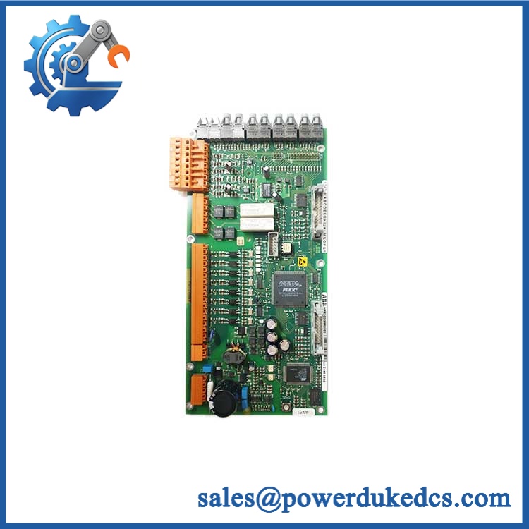
ABB UAB016BE HIEE200114R1
Module 4: Dynamic Emergency Swap & Configuration Guide
1. Pre-Swap Prep — establish the protection baseline
Place the affected drive or power-control cabinet in the plant-approved maintenance state and complete the required LOTO procedure. Photograph the UAB016BE nameplate, board orientation, connectors, LED states, mounting position, and adjacent electronics. Record HIEE200114R1, hardware revision, installed configuration, and any ground-fault threshold or alarm information available from the controller. Use ESD protection and a calibrated multimeter.
2. Removal — preserve the sensing and interface connections
After confirming the required isolation and absence of hazardous voltage, label each connector before removal. Record the connector arrangement against the cabinet schematic. Release the board from its retaining hardware and withdraw it straight from the rack, carrier, or backplane. Inspect the mating interface for contamination, bent contacts, corrosion, or heat damage before installing the spare.
3. Installation & Configuration — restore the original protection arrangement
Install the replacement UAB016BE in the same physical position and secure it correctly. Reconnect all interfaces exactly according to the original wiring documentation. Confirm the supply specification from the cabinet schematic before energizing. Restore any board-related configuration, sensing parameters, alarm thresholds, addresses, or controller-side protection settings from the validated maintenance backup. Do not assume another UAB-series board is interchangeable because its mechanical dimensions are similar.
4. Power-On Self-Test (POST) — verify monitoring before enabling equipment
Restore power according to the approved commissioning procedure. Observe all available status, run, warning, and fault indications during initialization. Confirm that the host system recognizes the without persistent diagnostics. Under a controlled test condition, verify the ground-fault monitoring channel, alarm path, trip/interlock logic where applicable, and return-to-normal behavior. The board should not be considered serviceable merely because its power indicator illuminates.
Module 5: Quality Assurance & Testing SOP
The should be tested as a protection and monitoring board, with emphasis on signal integrity and alarm behavior.
- OEM Anti-Counterfeit Visual Inspection: Verify ABB markings, designation, HIEE200114R1 part number, PCB layout, connector geometry, component placement, labels, and revision markings.
- Serial and Identity Traceability: Photograph the complete nameplate and record all visible serial and revision information.
- Mechanical Inspection: Examine PCB edges, mounting points, connectors, retaining hardware, and card guides for mechanical damage.
- Power Verification: Apply the verified cabinet supply under controlled laboratory conditions and monitor startup behavior.
- Power-On Self-Test (POST): Record startup sequence and all available RUN, status, warning, and fault indicators.
- Controller Recognition Test: Confirm that the connected control system correctly identifies the installed board.
- Ground-Fault Signal Test: Apply a controlled representative sensing signal and verify the monitoring channel responds correctly.
- Alarm Simulation: Introduce an approved simulated fault condition and verify expected alarm generation.
- Trip/Interlock Test: Where the installation uses a protection trip or interlock output, verify the complete signal path under controlled test conditions.
- Threshold Verification: Compare measured pickup or alarm behavior against the actual system documentation rather than an assumed generic setting.
- Reset Verification: Confirm correct return-to-normal behavior after the simulated fault is cleared.
- Communication/Diagnostic Test: Verify all applicable controller diagnostics and communication paths.
- Extended Powered Test: Monitor the board for intermittent alarms, resets, communication loss, or abnormal temperature.
- Final QC Record: Document board identification, test conditions, measured values, simulated-fault results, photographs, and technician approval.
Because publicly available information for is limited and inconsistent, the customer’s original ABB system documentation should establish the final electrical and protection acceptance limits. Available records do support the ground-fault monitoring classification.
Module 6: Maintenance & Reliability FAQ
1. Is the HIEE200114R1 a direct drop-in replacement, or does it require a firmware flash?
Do not assume direct interchangeability from the designation alone. Verify the complete / identification, hardware revision, mounting position, connector arrangement, and controller configuration. There is no reliable public evidence establishing a universal firmware procedure for this specific legacy board.
2. Is it safe to hot-swap this monitoring board while the system is running?
Do not assume that live replacement is permitted. A ground-fault monitoring board may interface with energized sensing and protection circuits. Unless the specific ABB cabinet documentation explicitly authorizes energized replacement, use the approved shutdown, isolation, and voltage-verification procedure.
3. Will replacing this board cause my current protection program to be lost?
Replacing the board itself does not necessarily replace the host controller’s application. However, board-specific settings, thresholds, channel assignments, or controller-side configuration can affect protection behavior. Back up the complete controller project, protection parameters, alarm settings, and wiring documentation before replacement.
4. What should I verify after installing the replacement?
Start with supply integrity and self-diagnostics. Then verify controller recognition, ground-fault sensing, alarm thresholds, trip/interlock signals where applicable, fault-reset behavior, and diagnostic reporting. A normal status LED is not sufficient evidence that the protection function is operating correctly.
5. What are the warranty terms if the unit fails post-installation?
Warranty should be tied to the supplied serial number and documented condition, whether factory-sealed, tested, or refurbished. Hardware defects should be distinguished from damage caused by incorrect wiring, overvoltage, ESD, incorrect protection settings, installation damage, or faults elsewhere in the sensing circuit. The exact warranty period and return procedure should be stated on the quotation before purchase.











 Start Chat


