

Description
- Brand: ABB
- Full Model Number: UAC326AE
- Ordering Number: HIEE401481R0001
- Lifecycle Status: Legacy ABB/Alstom excitation-system installed base
- Core Function in System: I/O interface for ABB/Alstom excitation control equipment
- Top 3 Hardcore Specs: 24 VDC control supply; excitation-system I/O interface; field-listed dual-core custom CPU architecture
- Typical System Association: GT11 / GT12 gas-turbine excitation systems
- Condition & Lead Time: Tested inventory or factory-sealed stock; emergency dispatch subject to confirmed availability
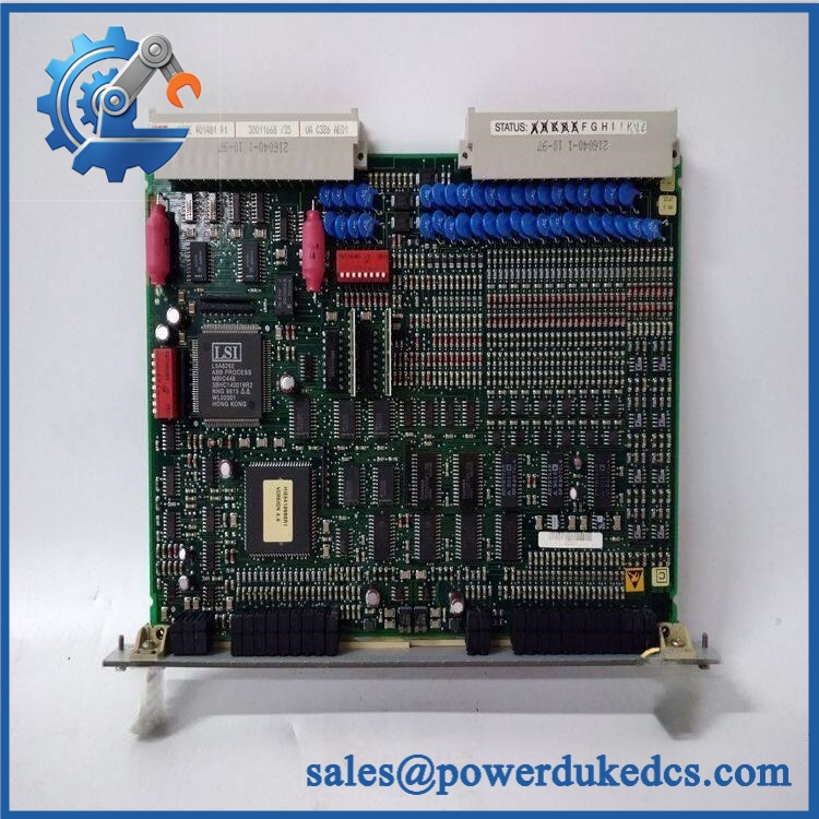
Field records identify the UAC326AE HIEE401481R0001 specifically as an I/O interface used in GT11 and GT12 excitation systems. Available technical listings also associate the unit with a 24 VDC supply and dual-core custom CPU architecture.
Module 3: Technical Intro & Downtime Impact
A 3 AM excitation-system fault does not always originate in the generator control logic itself. A defective UAC326AE interface can interrupt signal exchange between the excitation controls and connected field equipment, making fault isolation difficult and potentially extending generator or turbine outage time. The UAC326AE, identified by ordering number HIEE401481R0001, is documented as an I/O interface associated with ABB/Alstom excitation systems, including GT11 and GT12 installations.
Replacement planning should center on exact hardware identification rather than a model-family match. Available inventory documentation lists 24 VDC operation, while one technical listing describes a dual-core custom CPU and user/I/O memory allocations. Because public listings for this legacy part contain conflicting electrical and functional descriptions, cabinet drawings, nameplate data, and the installed hardware revision should be treated as the controlling references before energization. —especially important where an excitation-system shutdown carries a high restart cost.
Module 4: Dynamic Emergency Swap & Configuration Guide
1. Pre-Swap Prep — document the excitation cabinet before touching the board
Secure the generator/turbine in the plant-approved maintenance state and isolate energy sources according to the site’s LOTO procedure. Photograph the existing UAC326AE, terminal wiring, plug positions, indicator states, and all identification labels. Record the exact ordering number, firmware or configuration data where accessible, and I/O channel assignments. Use ESD protection and a calibrated multimeter for supply verification.
2. Removal — disconnect the interface wiring without disturbing adjacent circuits
Verify the cabinet is de-energized unless the OEM-approved maintenance procedure explicitly permits energized replacement. Label each field connector before removal. Release the board or interface assembly from its mounting hardware, withdraw it straight from its mating connector, and inspect the socket, terminal contacts, and surrounding wiring for oxidation, heat discoloration, or loose conductors. The UAC326AE is identified in field documentation as an excitation-system I/O interface, so connector traceability matters more than a simple visual part-number match.
3. Installation & Configuration — reproduce the original signal architecture
Install the replacement in the same mechanical orientation and reconnect every terminal according to the original cabinet drawing. Confirm the 24 VDC supply polarity and measured voltage before applying power. Restore address, configuration, I/O mapping, and any board-specific settings from the documented site configuration. Do not substitute another listing solely because the front label looks similar; HIEE401481R0001 should be checked against the customer’s installed hardware record.
4. Power-On Self-Test (POST) — verify control-system behavior, not just illumination
Apply control power and observe all available status LEDs for normal initialization. Check for persistent fault or diagnostic indications, confirm the excitation controller recognizes the interface, then verify each connected signal path under a controlled test condition. Confirm permissives, feedbacks, and excitation-related alarms return to the expected state before the generator is released to operation. Where the cabinet provides no meaningful LED diagnostic pattern, use the engineering interface and controller diagnostics as the primary acceptance criteria.
Module 5: Quality Assurance & Testing SOP
Each should pass a documented inspection sequence before shipment.
- OEM Anti-Counterfeit Visual Inspection: Compare ABB/Alstom markings, ordering number, PCB layout, connectors, labels, fasteners, and identification codes against verified reference hardware.
- Serial and Part-Number Traceability: Record the exact / HIEE401481R0001 identification and photograph the nameplate.
- Mechanical Inspection: Check connector bodies, PCB edges, mounting points, terminal interfaces, and enclosure surfaces for impact or corrosion damage.
- Power Verification: Apply a controlled DC supply and verify correct operating voltage behavior before extended testing. Available field listings specify 24 VDC.
- Power-On Self-Test (POST): Record startup behavior and check all available RUN, status, fault, or diagnostic LEDs.
- Controller Communication Check: Confirm the test system recognizes the unit and that expected diagnostic information is available.
- I/O Full-Range Simulation: Exercise applicable input and output channels through their documented operating states, checking both command and feedback paths.
- Signal Integrity Test: Verify terminal-to-channel continuity and absence of unexpected cross-channel behavior.
- Thermal Observation: Monitor the unit during an extended powered run for abnormal temperature rise, unstable operation, or intermittent faults.
- Final QC Record: Attach the serial number, inspection photographs, test results, configuration notes, and packaging sign-off to the shipment record.
One field source identifies the specifically as an excitation-system I/O interface for GT11/GT12 gas-turbine installations, which is why I/O simulation should be performed against the actual system function rather than using a generic PLC acceptance test.
Module 6: Maintenance & Reliability FAQ
1. Is the HIEE401481R0001 a direct drop-in replacement, or does it require a firmware flash?
Do not assume a universal drop-in replacement. This is a legacy excitation-system component, and available public records describe it in different ways. Match the designation, ordering number, hardware revision, cabinet configuration, and installed software before replacement. A firmware change should only be performed when the applicable ABB/Alstom documentation specifically requires it.
2. Is it safe to hot-swap the while the system is running?
There is insufficient verified OEM evidence to classify this specific unit as universally hot-swappable. Treat it as a de-energized replacement unless the applicable excitation-system maintenance manual explicitly permits energized extraction and insertion for your exact cabinet configuration.
3. Will replacing this interface cause my current configuration to be lost?
The hardware replacement itself does not automatically mean the complete excitation-system configuration disappears, but the replacement can still fail to operate correctly if required parameters, I/O assignments, or controller-side configuration are missing. Back up the complete project, configuration files, parameter sets, and relevant terminal documentation before the outage whenever the installed system allows it.
4. What should I verify before returning the generator to service?
Confirm 24 VDC supply polarity and voltage, every field connection, controller diagnostics, excitation feedback, permissives, alarm status, and all tested I/O channels. A successful power-up alone is not enough; the excitation control loop must respond correctly under the plant’s approved functional test procedure.
5. What are the warranty terms if the replacement fails after installation?
For industrial surplus or tested inventory, the warranty should be tied to the supplied serial number and documented condition. A typical hardware warranty excludes incorrect wiring, overvoltage, ESD damage, unauthorized modification, and installation or configuration errors. The exact warranty period and failure-return procedure should be stated on the quotation before purchase.











 Start Chat


