

Description
- Brand: ABB
- Full Model Number: UCU-26 / 3AXD50000645770
- Product Type: Converter Control Unit
- Lifecycle Status: Current UCU control platform; exact drive application and programmed configuration require verification
- Core Function in System: Central control unit for ABB medium-voltage and high-power converter systems with fiber-optic module interfaces
- Top 3 Hardcore Specs: External 24 VDC supply | 26 fiber-optic connections via 2 × UPEB-12 boards | 3 optional expansion slots
- Memory / Data: Removable microSDHC memory unit for parameter retention and real-time data storage
- Communications: XD2D RS-485 drive-to-drive link | Optional RDCO DDCS interface
- Control Panel Connection: RJ45 Ethernet connection
- Compatible Platforms: ACS6080, ACS6000 modernization and other ABB converter applications using the UCU-26 platform
- Condition & Lead Time: New or verified surplus inventory subject to configuration and stock confirmation; expedited dispatch available for stocked units
ABB’s UCU-26 hardware manual identifies the device as a converter control unit with an external 24 VDC supply, three optional slots, a removable memory unit, and 26 fiber-optic connections provided by two UPEB-12 boards. ABB also states that the control unit contains integrated branching-unit functionality for collecting and storing real-time converter data.
Module 3: Technical Intro & Downtime Impact
A failed UCU-26 can stop supervisory control of multiple converter modules even when the power electronics and field wiring remain intact. That is especially significant on large ACS6000 or ACS6080 installations, where the control unit manages fiber-optic communication with converter modules and provides the central interface for diagnostics and control. ABB describes the UCU-26 as a control unit with integrated branching functionality that collects and stores real-time data from connected modules for fault analysis.
From an MTTR perspective, the most important specifications are the 24 VDC external supply, 26 optical connections, and removable memory architecture. Two UPEB-12 boards provide the 26 optical interfaces, while the unit has three optional slots for I/O, encoders, or fieldbus adapters. The XD2D interface is an RS-485 daisy-chain used for basic master/follower communication, and an optional RDCO DDCS board can provide additional optical communication. A particularly useful recovery feature is ABB’s statement that the memory unit can be moved from a defective UCU to the replacement unit to retain parameter settings. That can materially reduce commissioning time… provided the replacement hardware and application are compatible.
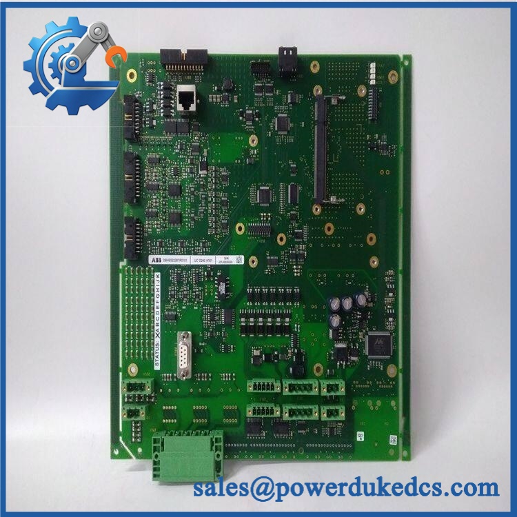
ABB UCU-26 3AXD50000645770
Module 4: Dynamic Emergency Swap & Configuration Guide
1. Pre-Swap Prep — Preserve the Memory Unit and Fiber Map
Apply the site’s approved LOTO procedure and remove auxiliary power from the UCU before service. Record the complete UCU-26 / 3AXD50000645770 identification, application type, firmware/software information, optional boards, all fiber connections V1–V26, XD2D connections, and control-panel Ethernet connection. Photograph the fiber routing carefully.
Before removing the defective control unit, identify the removable microSDHC memory unit. ABB specifically states that parameter settings can be retained by moving the memory unit from the failed UCU to the replacement.
2. Removal — Disconnect the UCU Without Disturbing Fiber Pairs
After auxiliary voltage has been safely removed, disconnect the RJ45 control-panel cable, XD2D wiring, optional fieldbus or I/O connections, and optical fiber pairs. Label every fiber before removal.
The uses two UPEB-12 boards for a total of 26 optical connections. ABB warns that connected fiber-optic pairs must use the same cable length, because differing propagation delays can adversely affect operation. Release the UCU’s mounting hardware and remove the control unit without bending or stressing the fiber connectors.
3. Installation & Configuration — Transfer the Memory and Reproduce the Hardware
Install the replacement in the same position and reconnect each fiber to its original port. Reconnect the control-panel Ethernet cable, XD2D line, optional I/O/encoder/fieldbus boards, and any RDCO DDCS interface in exactly the same configuration.
Move the approved microSDHC memory unit from the failed UCU to the replacement when the service procedure calls for parameter retention. ABB explicitly identifies the removable memory unit as the mechanism for retaining parameter settings during a UCU replacement.
Do not assume that a with the same ordering number is fully interchangeable without checking the installed application and option hardware. The control unit can host three optional expansion slots, so the installed configuration directly affects compatibility.
4. Power-On Self-Test (POST) — Verify Power, Memory, and Optical Communication
Restore the external 24 VDC supply and monitor the unit’s diagnostic LEDs. ABB documents the with a PWR indication for adequate supply voltage, a BAT indication associated with the real-time-clock battery, a WRITE indication for microSDHC activity, and a FAULT indication when the control program generates a fault.
Do not remove the microSDHC card while the WRITE indicator is active. ABB’s maintenance documentation identifies that state as memory-card write activity. After normal startup, verify control-panel communication, all required optical links, module visibility, converter diagnostics, and the drive application before returning the equipment to service.
Module 5: Quality Assurance & Testing SOP
Each available ABB / 3AXD50000645770 should undergo a controlled hardware and application-verification procedure before shipment:
- OEM anti-counterfeit visual inspection — verify ABB markings, identification, serial label, PCB construction, connector quality, and manufacturing markings.
- Part-number reconciliation — match the physical control unit against 3AXD50000645770 and the customer’s converter BOM.
- Hardware configuration audit — document both UPEB-12 boards, all 26 optical ports, optional slot occupancy, RDCO installation, memory-unit type, and connector condition.
- Memory-unit inspection — verify the removable microSDHC unit is present and identify its condition before shipment. ABB documents this memory unit as a means of retaining parameter settings during control-unit replacement.
- 24 VDC power test — apply a controlled external 24 VDC supply and verify stable startup.
- Power-on self-test (POST) checking for PWR, BAT, WRITE, and FAULT LEDs — record the complete LED sequence and steady-state condition.
- Fiber-optic communication test — verify all required optical channels using a compatible ABB converter test environment. The supports 26 optical connections through two UPEB-12 boards.
- Fiber-length consistency check — confirm each connected fiber pair meets the applicable cable-length requirement and that paired connections use equal lengths. ABB explicitly warns about delay differences from unequal fiber lengths.
- Control-panel communication test — connect a compatible control panel via the RJ45 Ethernet interface and confirm normal communication.
- XD2D communication test — verify the RS-485 master/follower interface where installed.
- Optional I/O and fieldbus test — exercise each installed expansion module and verify that the UCU recognizes the hardware.
- Real-time data acquisition test — confirm that the control unit collects expected module data and that diagnostic information can be stored through the memory architecture.
- Fault simulation — where the laboratory setup permits, disconnect a controlled communication channel and verify appropriate diagnostic reporting and recovery.
- Extended run test — operate the UCU continuously under representative converter communication traffic and monitor power stability, optical communication, temperature, and diagnostic status.
- Final QA record — retain identification photos, software information, option-board inventory, memory-unit status, LED results, optical-port test results, communication results, and final packing photos.
ABB’s hardware documentation also notes maximum optical cable lengths of 35 m for 1 mm plastic optical fiber and 100 m for 200 μm hard-clad silica fiber. These limits should be checked against the actual installation before commissioning.
Module 6: Maintenance & Reliability FAQ
Is the ABB 3AXD50000645770 a direct drop-in replacement, or does it require a firmware flash?
It can be a direct hardware replacement when the application, option boards, firmware, and memory configuration match. The itself is a platform rather than a universal application package. The removable memory unit is important because ABB states that moving it to the replacement UCU can retain parameter settings. Verify the exact converter application before installation.
Is it safe to hot-swap the while the system is running?
Do not assume hot-swapping is permitted. The UCU has an external 24 VDC supply and multiple electrical and optical interfaces, and the applicable converter safety procedure controls whether energized replacement is allowed. For an emergency replacement, isolate the relevant control power under the site’s approved maintenance procedure unless ABB documentation for the exact system explicitly authorizes live replacement.
Will replacing the cause my current program or parameters to be lost?
The replacement does not necessarily require rebuilding the parameter set from scratch. ABB explicitly states that the memory unit can be transferred from the defective control unit to the new control unit to keep parameter settings. Even so, maintain an independent backup of converter parameters and application data before planned maintenance. That protects against a damaged memory card, configuration mismatch, or unrelated fault during commissioning.
What should I verify before ordering an emergency ?
Confirm / 3AXD50000645770, the exact converter family, application firmware, number and type of boards, optional I/O or encoder modules, RDCO configuration, memory-unit type, and the required fiber-port assignment. The supports 26 optical connections, three optional slots, RS-485 communication, and an optional RDCO DDCS interface. A clear photograph of the installed unit and its connector layout is highly useful for configuration matching.
What are the warranty terms if the unit fails after installation?
Warranty depends on the supplying party, stock condition, and purchase agreement. Confirm the warranty duration, DOA coverage, test scope, and return procedure before shipment. Retain the pre-shipment QA report and installation records, including the original UCU identification, memory-unit status, fiber-port mapping, LED results, and post-installation diagnostic screenshots. Those records make it much easier to distinguish a defective control unit from a fiber, configuration, or converter-side fault.











 Start Chat


