

Description
- Brand: ABB
- Full Model Number: UFC760BE145
- ABB Part Number: 3BHE004573R0145
- ABB Type Designation: UF C760 BE145: INU-INT
- Product Type: Phase Modulator / INU Interface Board
- Lifecycle Status: Legacy ABB medium-voltage drive installed-base component
- Core Function in System: Interface and phase-modulation circuitry for an INU frequency-converter power stage
- Top 3 Hardcore Specs: UF C760 BE145 designation; INU-INT interface function; ABB frequency-converter application
- System Association: ABB ACS5000 / related medium-voltage frequency-converter architecture
- Primary Role: Inverter interface and phase modulation
- Board Class: Control/power-interface PCB
- Condition & Lead Time: Tested inventory or factory-sealed stock; emergency dispatch subject to confirmed availability
ABB’s parts catalog identifies 3BHE004573R0145 as UF C760 BE145: INU-INT; PHASE MODULATOR. Other ABB parts records place the same component within the ACS5000 drive family.
Module 3: Technical Intro & Downtime Impact
A phase-modulator failure can prevent a medium-voltage frequency converter from developing the correctly controlled switching pattern required by the inverter power stage. Symptoms may appear as inverter initialization faults, missing gate-drive activity, converter trips, or abnormal power-stage diagnostics. ABB UFC760BE145 3BHE004573R0145 is identified as the UF C760 BE145 INU-INT phase modulator, so this is a power-stage interface component rather than a generic I/O board.
The available records do not provide a sufficiently verified OEM dataset for publishing exact switching frequency, supply rails, output levels, or environmental limits for this particular revision. Those values should come from the installed drive documentation. What can be established is the component’s function and designation: INU-INT, Phase Modulator. In an emergency repair, the key MTTR controls are exact part-number matching, correct inverter position, connector orientation, gate/interface wiring, and post-replacement verification of the power-stage control path. —a visually similar C760 board is not automatically interchangeable.
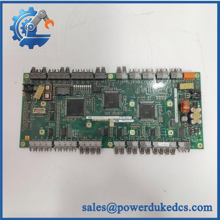
ABB UFC760BE145 3BHE004573R0145
Module 4: Dynamic Emergency Swap & Configuration Guide
1. Pre-Swap Prep — identify the exact inverter interface before isolation
Place the medium-voltage converter in the plant-approved maintenance state and complete the applicable LOTO procedure. Verify that the main input, DC-link, and associated power-stage circuits have reached the required safe voltage condition. Photograph the UFC760BE145 and 3BHE004573R0145 markings, board orientation, connector positions, cable routing, and adjacent inverter electronics. Record the drive model, inverter section, hardware revision, and any diagnostic codes present before shutdown.
2. Removal — protect the phase-modulator and gate-interface connections
After confirming absence of hazardous voltage, label each connector against the drive schematic. Disconnect the control and interface wiring without pulling on the PCB or cable harness. Release the board from its carrier or mounting arrangement and withdraw it squarely from the mating interface. Inspect the connector contacts, card guides, and adjacent gate-control hardware for contamination, arcing, loose contacts, or thermal damage. A failed phase-modulator board can also be a secondary casualty of a power-stage fault, so inspect the surrounding circuitry before installing the spare.
3. Installation & Configuration — preserve the original INU interface arrangement
Install the replacement UFC760BE145 in the same position and secure all mechanical retainers. Reconnect the wiring exactly according to the original inverter schematic. Confirm that the board designation is UF C760 BE145: INU-INT and that the replacement matches the required inverter configuration. Do not substitute other variants such as BE141, BE142, or BE143 solely because they share the same basic board family; ABB assigns those variants different functions.
4. Power-On Self-Test (POST) — validate switching control before loading the drive
Restore control power using the approved commissioning procedure and inspect all available diagnostic indications. Confirm correct initialization of the inverter control system and absence of phase-modulator or gate-interface faults. Where the approved test procedure permits, verify the gate/control interface using a suitable test fixture before enabling the power stage. Check inverter diagnostics, current feedback, switching-related alarms, and phase consistency before applying normal motor load.
Module 5: Quality Assurance & Testing SOP
The UFC760BE145 requires a board-level inspection followed by controlled inverter-interface testing.
- OEM Anti-Counterfeit Visual Inspection: Verify ABB markings, UFC760BE145, 3BHE004573R0145, UF BE145 designation, connector layout, component placement, and revision markings.
- Serial and Identity Traceability: Photograph the complete board identification and record all available serial and revision information.
- Mechanical Inspection: Check PCB edges, mounting points, card guides, connector housings, retaining hardware, and interface contacts.
- PCB Condition Inspection: Check for burnt components, cracked solder joints, carbon tracking, discoloration, corrosion, and contamination.
- Power-On Self-Test (POST): Apply the approved control supply through a controlled test fixture and record startup behavior and diagnostic status.
- INU Interface Test: Verify the board’s interface to the associated inverter control circuitry using the applicable ABB test procedure.
- Phase-Modulation Verification: Confirm correct control-signal generation at the approved test points and compare against the applicable engineering specification.
- Gate/Control Path Check: Verify continuity and signal integrity across the board-to-power-stage interface where the test setup supports it.
- Protection Check: Test applicable interlock, inhibit, fault-detection, and shutdown paths under controlled conditions.
- Feedback Correlation: Verify that inverter current and status feedback remain consistent with the commanded test state.
- Phase Consistency Test: Check equivalent control paths for unexpected amplitude, timing, or phase discrepancies.
- Fault Simulation: Introduce approved interface faults and confirm that the host drive generates the expected diagnostics.
- Extended Powered Test: Monitor for unstable signals, intermittent faults, abnormal heating, or unexpected resets during an extended run.
- Final QC Record: Document the exact board identity, inverter compatibility, test fixture, measured values, diagnostic results, photographs, and QC approval.
ABB records distinguish from neighboring variants: BE141 is listed as an ARU interface board, BE142 as an INU interface board, BE143 as a PUB/PFF interface board, while is specifically identified as the INU-INT phase modulator. That distinction should be preserved throughout inspection and procurement.
Module 6: Maintenance & Reliability FAQ
1. Is the 3BHE004573R0145 a direct drop-in replacement, or does it require a firmware flash?
It is a phase-modulator / INU interface board, not the primary application controller, so a conventional firmware flash is not normally the first replacement concern. The critical checks are the exact identification, inverter position, hardware revision, connector configuration, and associated power-stage architecture.
2. Is it safe to hot-swap this board while the drive is running?
No general hot-swap assumption should be made. This board interfaces with a medium-voltage inverter power stage. Follow the exact drive maintenance procedure, isolate hazardous energy, and verify the DC link and associated circuits are at the prescribed safe voltage before removal.
3. Will replacing this phase-modulator board cause my current drive program to be lost?
Replacing the does not normally replace the main drive application or parameter set. Nevertheless, back up the complete drive configuration, commissioning data, hardware settings, and diagnostic records before intervention. The replacement must reproduce the correct inverter hardware arrangement.
4. What should I verify after installing the replacement?
Confirm the exact board designation first. Then verify controller recognition, inverter diagnostics, phase-modulation behavior, gate/interface signals, current feedback, interlocks, and fault reporting. The drive should undergo the approved no-load or commissioning sequence before full process loading.
5. What are the warranty terms if the unit fails post-installation?
Warranty should be tied to the supplied serial number and documented stock condition. Hardware failure should be distinguished from damage caused by incorrect installation, incompatible inverter hardware, power-stage faults, overvoltage, ESD, contaminated connectors, or unauthorized modification. The exact warranty period and return procedure should be stated on the quotation before purchase.











 Start Chat


