

Description
- Brand: ABB
- Full Model Number: UFC760BE145
- ABB Part Number: 3BHE004573R0145
- Product Type: INU internal interface / phase modulator board
- Product Family: ABB ACS 600 / industrial drive electronics
- Core Function in System: Interface and modulation functions associated with the inverter unit
- Board Designation: UFC760BE145
- Internal Interface: INU interface
- Application: ABB inverter/drive power-electronics assemblies
- Form Factor: Drive internal PCB assembly
- Dimensions: Approx. 33 × 16 × 2 cm reported by secondary inventory data
- Weight: Approx. 0.36 kg reported by secondary inventory data
- Condition & Lead Time: Stock condition subject to inspection; emergency dispatch available subject to order confirmation
ABB-related parts catalogs identify 3BHE004573R0145 as UFC760BE145, with the catalog description “UF C760 BE145: INU-INT; PHASE MODULATOR.” The same catalog separates the related UFC760 variants by function: BE141 is an ARU interface board, BE142/BE143 are other interface boards, and BE145 is associated with the INU/phase-modulator function.
Identification note: public secondary sources sometimes describe this board generically as a frequency I/O board or phase modulator. For a procurement record, the more specific catalog designation “INU-INT; PHASE MODULATOR” is preferable.
Module 3: Technical Intro & Downtime Impact
A failed inverter interface or modulation board can stop a drive at the power-conversion layer even when the control program and operator interface remain online. The result may be an inverter fault, loss of gating/modulation, incorrect feedback behavior, or an inability to enable the motor. ABB UFC760BE145, 3BHE004573R0145, is cataloged as an INU internal interface / phase modulator board, placing it within the inverter-side electronics rather than the general control-network layer.
For MTTR, exact board identity is more important than a generic “UFC760” match. ABB-related catalog data distinguishes BE145 from other UFC760 interface variants, so swapping in another UFC760 board simply because the connector arrangement looks similar is not a safe repair strategy. Secondary inventory data reports approximately 33 × 16 × 2 cm and 0.36 kg, but I could not verify those figures through a primary ABB technical document. Likewise, I did not find a sufficiently authoritative source establishing exact supply voltage, operating-temperature range, gate-signal characteristics, or board-level MTBF for this specific UFC760BE145 revision. Those values should come from the host drive manual and electrical drawings.
Module 4: Dynamic Emergency Swap & Configuration Guide
1. Pre-Swap Prep — Capture the Inverter Hardware State
Place the drive into the approved maintenance state and isolate all incoming power. Verify DC-link discharge with an appropriately rated meter before opening the power section. Record the complete UFC760BE145 / 3BHE004573R0145 identification, board revision, host drive type, inverter-unit position, connector locations, fiber/control connections, and fault history. Photograph the original board before disconnecting any wiring.
2. Removal — Disconnect the Board Without Disturbing Power Electronics
is an internal inverter interface/phase-modulator board, not a DIN-rail device. Remove cabinet covers only after the DC bus has been proven safe. Label every connector and optical/electrical interface, then release the board-retention hardware and withdraw the PCB using its designated handling points.
Do not pull on fiber-optic cables or small signal conductors. Avoid contact with adjacent power semiconductor assemblies and heatsinks. The board may be electrically linked to gate-control or measurement circuitry, so preserving connector orientation and cable routing is essential.
3. Installation & Configuration — Match the Exact UFC760 Variant
Before installing the replacement, verify and 3BHE004573R0145 against the removed board. Catalog records identify BE145 specifically as the INU internal-interface/phase-modulator variant.
Install the replacement in the same mechanical position and reconnect every interface according to the drive schematic. Do not interchange it with UFC760BE141, BE142, or BE143 simply because those parts share the UFC760 family designation; available catalog data assigns those variants different functions. No board-level firmware operation should be assumed unless the host-drive service documentation explicitly requires one.
4. Power-On Self-Test (POST) — Validate the Inverter Before Motor Release
After the cabinet has been inspected and all covers or barriers required for energized testing are restored, reapply power according to the drive commissioning procedure. Check the drive diagnostic display for inverter-unit faults and confirm that the replacement board is not generating communication, modulation, or feedback alarms.
Perform a controlled enable test before connecting the motor to full process load. Verify the inverter’s feedback, current response, gating/modulation status, and fault-free behavior during a low-risk run. A normal control-panel startup is not enough; the inverter must demonstrate stable power-stage control.
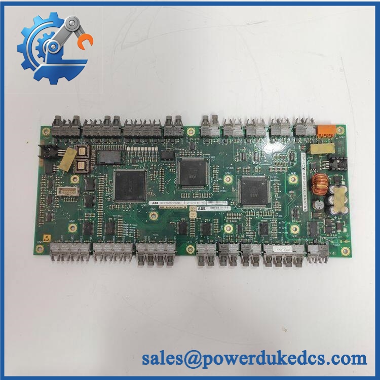
ABB UFC760BE145 3BHE004573R0145
Module 5: Quality Assurance & Testing SOP
Each ABB / 3BHE004573R0145 should undergo board-level inspection and host-drive functional testing before shipment.
- OEM anti-counterfeit visual inspection: Check ABB markings, designation, 3BHE004573R0145 identification, PCB layout, connectors, optical interfaces, component quality, and revision markings.
- Exact part-number verification: Confirm the complete identity against the inventory record and physical board.
- Mechanical inspection: Examine PCB edges, mounting points, connector pins, optical interfaces, standoffs, contamination, corrosion, solder condition, and evidence of unauthorized modification.
- Host compatibility verification: Confirm the board is being tested in a drive/inverter assembly that specifically uses the BE145 interface variant.
- Power-on self-test (POST): Energize the compatible drive test assembly under controlled conditions and verify startup diagnostics.
- Interface continuity test: Check accessible low-voltage interface paths against the approved drive schematic before full energization.
- Modulation-interface test: Verify the board’s interface to the inverter-control/power stage using the OEM-approved test procedure.
- Feedback test: Confirm that inverter current/measurement feedback paths produce expected values without intermittent errors.
- I/O full-range simulation: Exercise applicable control and feedback signals across the approved laboratory range.
- Optical-interface inspection: Where fiber links are used, inspect connectors for contamination and verify transmit/receive integrity with the appropriate test equipment.
- Drive-enable test: Execute controlled start/stop cycles and monitor inverter diagnostics, current response, speed feedback, and fault behavior.
- Repeated-cycle test: Perform multiple enable/disable and controlled acceleration/deceleration cycles to expose intermittent interface faults.
- Thermal observation: Monitor board and adjacent inverter electronics for abnormal temperature rise during representative operation.
- Extended stability test: Maintain representative drive operation and record resets, inverter faults, feedback deviations, or intermittent modulation faults.
- Final QC record: Document board identity, revision, host drive type, connector configuration, test conditions, diagnostic results, operating observations, photographs, technician sign-off, and packaging condition.
Module 6: Maintenance & Reliability FAQ
1. Is ABB a direct drop-in replacement, or does it require a firmware flash?
Treat as a hardware-specific inverter interface board. The available catalog identifies it as an INU interface / phase modulator, not a general-purpose CPU. A firmware flash should not be assumed as part of a normal board replacement. Verify the host drive model, board revision, and associated firmware requirements before commissioning.
2. Is it safe to hot-swap while the drive is running?
No. This board belongs inside the inverter power-electronics assembly. The DC link and associated power-stage circuits can retain hazardous energy after incoming power is removed. Isolate the drive, verify DC-bus discharge with an approved instrument, and follow the host-drive service procedure before accessing the board.
3. Will replacing cause my current program or drive parameters to be lost?
The board is associated with the inverter interface/modulation function rather than being the primary application-memory controller. Replacing it should not by itself erase the main drive application. Nevertheless, back up the drive parameters, motor data, control configuration, fault history, and any commissioning-specific calibration values before shutdown.
4. What should I verify before commissioning the replacement?
Verify , 3BHE004573R0145, host-drive compatibility, board revision, connector layout, optical connections where applicable, and the exact inverter position. Also confirm that the replacement is not one of the related variants assigned to another function. ABB-related catalog data specifically differentiates BE141, BE142, BE143, and BE145 by function. Perform a controlled inverter test before releasing the motor to production.
5. What are the warranty terms if the unit fails after installation?
Warranty coverage should be stated on the quotation or sales order for the specific serialized board. Retain the incoming inspection record, board photographs, host-drive identification, pre-replacement fault history, post-installation diagnostics, and controlled run-test results. For inverter interface hardware, that evidence helps distinguish a defective board from a power-stage, feedback, fiber-optic, control-cabling, or parameter problem.











 Start Chat


